Reference no: EM132509422
MIME1423 Mechanics of machines II - Higher College Of Technology
Section - 1
Ali, a young engineer is planning to design a speed reduction box using gear train. The input shaft will be driven by an induction motor running at 3000 rpm. The output speed of the reduction box is 1.5 rpm and the direction of rotation of the shaft is same as that of input. The input and output shafts are oriented as shown in the adjoining fig.

The reduction steps are limited to 3 and to be designed for a quiet operation. In each step of speed reduction, 5% of power loss is assumed.
a) Draw neat schematic diagram in three different views (Front, Top and left/right side) to illustrate the orientation and type of the gears used in the reduction box.
b) List all the components and label them properly.
c) Identify input and output shafts. Give reasons.
Section - 2
Refer Part-1 to answer the following
d) Find torque and power of output gear after each step of reduction.
e) Find train value of the speed reduction box.
f) Explain the working of speed reduction box in an engineering application.
Section - 3
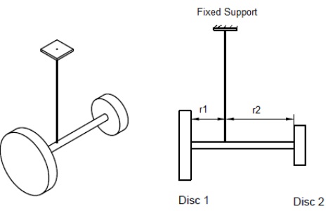
A heavy disc of diameter 12 cm spins about a horizontal shaft of length 120 cm as shown in
the figure. Another heavy disc of 6 cm in diameter is used as a counter weight to the first disc also spins about the same shaft. Two discs are possessing different masses and they are kept at different positions from the point of suspension as shown. The shaft rotates anticlockwise (observed from top) at 1500 rpm about the point of suspension. To keep the shaft horizontal always, evaluate the following
a) Moment of inertia of the discs about its own axis.
b) Distance of the discs from the point of suspension
c) Direction of rotation of discs about shaft axis.
d) Torque required to keep the shaft horizontal during rotation.
Section - 4
The Table Part-4 given below lists the output torque on flywheel with rotation of the crank shaft for a single-cylinder engine running at 4600 rev/min.
a) Draw a turning moment diagram.
b) Find the mean output torque. [hint: Find area under the graph]
c) Determine the mass moment of inertia of an appropriate flywheel using Cs = 0.025.
d) Maximum and minimum angular speed of the flywheel.
|
TABLE-PART- 4
|
|
CRANK ANGLE
|
OUTPUT TORQUE
|
CRANK ANGLE
|
OUTPUT TORQUE
|
CRANK ANGLE
|
OUTPUT TORQUE
|
CRANK ANGLE
|
OUTPUT TORQUE
|
|
deg
|
N-m
|
deg
|
N-m
|
deg
|
N-m
|
deg
|
N-m
|
|
0
|
0
|
180
|
0
|
360
|
0
|
540
|
0
|
|
10
|
17
|
190
|
-344
|
370
|
-145
|
550
|
-344
|
|
20
|
812
|
200
|
-540
|
380
|
-150
|
560
|
-540
|
|
30
|
963
|
210
|
-576
|
390
|
7
|
570
|
-577
|
|
40
|
1016
|
220
|
-570
|
400
|
164
|
580
|
-572
|
|
50
|
937
|
230
|
-638
|
410
|
235
|
590
|
-643
|
|
60
|
774
|
240
|
-785
|
420
|
203
|
600
|
-793
|
|
70
|
641
|
250
|
-879
|
430
|
490
|
610
|
-893
|
|
80
|
697
|
260
|
-814
|
440
|
424
|
620
|
-836
|
|
90
|
849
|
270
|
-571
|
450
|
571
|
630
|
-605
|
|
100
|
1031
|
280
|
-324
|
460
|
814
|
640
|
-379
|
|
110
|
1027
|
290
|
-190
|
470
|
879
|
650
|
-264
|
|
120
|
902
|
300
|
-203
|
480
|
785
|
660
|
-300
|
|
130
|
712
|
310
|
-235
|
490
|
638
|
670
|
-368
|
|
140
|
607
|
320
|
-164
|
500
|
570
|
680
|
-334
|
|
150
|
594
|
330
|
-7
|
510
|
576
|
690
|
-198
|
|
160
|
544
|
340
|
150
|
520
|
540
|
700
|
-56
|
|
170
|
345
|
350
|
145
|
530
|
344
|
710
|
-2
|
Section - 5
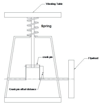
The resultant toque acting on a flywheel of mass 600 kg and diameter 80 cm, attached to a four stroke multi-cylinder engine is 8 sin 2θ - 6.5 sin θ kN-m, where θ is crank angle. The coefficient of fluctuation of speed is 2.25%. The flywheel is coupled with a vibrating table as shown in the figure given below. The force developed by the vibration table is limited to 200
N. Design the following,
a) Mass of the crank pin.
b) Offset distance of crank pin from the axis of the crank shaft.
c) Derive a relation connecting stiffness constant of the spring that supports vibrating table, mass and offset distance of the crank pin, speed of flywheel force developed.
d) Also, draw a turning-moment diagram of the flywheel.