Reference no: EM132378458
MIET1077 Mechanics of Machines Assignment - School of Engineering, RMIT University, Australia - Kinematic and Dynamic Analysis of Linkage Mechanisms
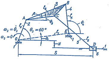
6-bar Linkage Mechanism - For the six-bar linkage mechanism shown below:
Given data:
|
l2 = OA
|
=
|
(m)
|
|
θ1
|
=
|
|
|
θ2
|
=
|
60o
|
|
β
|
=
|
|
|
n2
|
=
|
rpm
|
Determine:
|
l1 = OE
|
=
|
(m)
|
|
l3 = AB
|
=
|
(m)
|
|
l4 = BE
|
=
|
(m)
|
|
l5 = CD
|
=
|
(m)
|
|
AC
|
=
|
(m)
|
|
H
|
=
|
(m)
|
|
θ3
|
=
|
|
|
θ4
|
=
|
|
|
θ5
|
=
|
|
Guidelines for choosing the remaining dimensions of the mechanism:
OE- = CD- = 4OA-
OA- + AB- < OE- + BE-
OA- + OE- < AB- + EB-
AC- = 3/5 AB-
H = ¼OA-
Answer the following questions:
1. Determine all possible positions of links and joints by graphical position analysis. Draw to scale all positions of joints for sixteen subsequent positions of link 2 and determine the limits of motion where appropriate. Identify and outline the paths of each moving joint.
2. Determine linear and angular velocities by graphical velocity analysis for the given position θ2 = 60o of the mechanism, as shown above. Draw to scale the velocity vector diagram encompassing all linear velocities to scale and present the results in a tabular form.
3. Determine all linear and angular accelerations by graphical acceleration analysis for the given position θ2 = 60o of the mechanism. Draw to scale the acceleration vector diagram encompassing all linear accelerations to scale and present the results in tabular form.
4. Determine all instantaneous centres of velocity for the given mechanism using Kennedy's rule, and velocities of joints A, B, C and D using identified instantaneous centres. Draw all instantaneous centres and velocities to scale on a separate diagram of the mechanism.
5. Obtain analytic solutions for positions, velocities and accelerations by vector loop equations and complex number notation and present the results in a tabular form. Compare these results with those obtained using the graphical approach. You should have good correlation.
6. Determine all dynamic forces at the joints for the given position of the mechanism using the analytical matrix method. Assume, for link 2: m2 = 1 kg, CG at OA/2, I2 = 0.002 kgm2; for link 3: m3 = 2.5 kg, CG at β/2 and AB/2, I3 = 0.008 kgm2; for link 4: m4 = 1.5 kg, CG at EB/2, I4 = 0.005 kgm2; for link 5: m5 = 1.8 kg, CG at CD/2, I5 = 0.006 kgm2; for slider 6: m6 = 0.9 kg and CG at D.
7. Determine the shaking force and moment, and work out analytically an optimal strategy for balancing of the given mechanism. Discuss the results.
8. Develop an equivalent computer model capable of simulating the motion of the given mechanism using software Working Model and compute and plot the paths, velocities and accelerations over one revolution of the crank at the given angular velocity ω. Also, find the pin forces, slider side loads and driving torque over one revolution. How do the results compare with those obtained using the graphical and analytical approaches?
Attachment:- Assignment Template.rar