Reference no: EM132379017
MGGGC7105 - Slope Stability Assignment - Slope Stability Analysis, Federation University, Australia
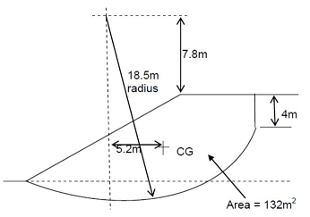
Question 1 - The following figure shows an embankment made in a homogenous clay medium. It is estimated that an open tension crack would develop down to a depth of 4m as shown. A likely circular failure surface is shown which gives an area of the failing soil as 132 m2. The location of the centre of gravity (shown as CG) of the failing soil is also shown. If the factor of safety (stabilising moment/destabilising moment) of the slope is 1.1, compute the undrained shear strength applicable to the failure surface. Assume that the tension crack is filled with water. The angle subtended at the centre by the circular arc is 72 degrees. The density of soil is 1860 kg/m3.
Question 2 - The following figure shows a slope stability analysis undertaken on a clay slope using the method of slices. The table gives some details of the analysis. Fill in the spaces of the table and compute the factor of safety for the slope. Use the equation for Ordinary (Swedish) method given by
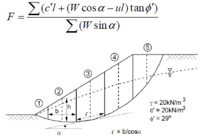
Note - W should be equal to bhγ.
|
Slice No.
|
b (m)
|
h (m)
|
W(bhγ) (kN/m)
|
α (deg)
|
Wcos α (kN/m)
|
Wsin α (kN/m)
|
u (m)
|
l (m)
|
ul (kN/m)
|
|
1
|
2
|
1
|
|
-13.2
|
|
|
0.45
|
|
|
|
2
|
4
|
3.2
|
|
-2.1
|
|
|
2.1
|
|
|
|
3
|
4
|
5.4
|
|
16.5
|
|
|
3.2
|
|
|
|
4
|
4
|
6.4
|
|
32
|
|
|
2.9
|
|
|
|
5
|
4.2
|
4
|
|
53.5
|
|
|
1.1
|
|
|
|
|
|
|
|
Sum
|
|
|
|
|
|
Question 3 - It is proposed to construct a canal in the ground shown in Figure for ferry transport (tile left bank is not shown).
Your task is to assess the canal banks stability for the following scenarios:
- Long-time after excavation of the canal without any water (in case of the operation of the canal has been delayed due to unforeseen events).
- During normal operation of the canal where the top water level of the canal is maintained at RL = 33 m for a long period of time.
- During the sudden draw down of the canal for urgent repair of sluice gate downstream.
The analysis is to be undertaken with the computer package "SLOPE/W". Use Bishop method as your analysis type.
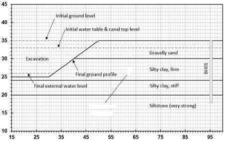
The proposed canal is 70.0m wide at the existing ground surface, with the side slopes of 2H:1V (horizontal: vertical). The top of the canal is at RL 35.0m for both banks. The deepest part of the canal is at RL 25.0m.
A summary of the soil profile, together with the soil properties is given in the following table (measured at borehole (BH01) located 95m back from top of each river bank). All soil layer interfaces can be assumed as horizontal. Normal operating water level of the canal is at RL = 33m.
|
RL (m) (BH1)
|
Soil description
|
Bulk density kN/m3
|
Cu kPa
|
C' kPa
|
Φ' Degrees
|
|
35 to 30
|
Gravity SAND (fill)
|
18.6
|
|
|
35
|
|
30 to 24
|
Silty CLAY, firm (CIS)
|
16.0
|
40
|
6
|
30
|
|
24 to 20
|
Silty CLAY, stiff (FBS)
|
17.8
|
70
|
12
|
32
|
|
< 20
|
SILTSTONE (very strong)
|
|
|
|
|
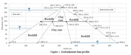
Question 4 - Staged construction is performed for Talbingo dam located on the Tumut River, Southern NSW:
- Stage 1 construction. The embankment is built to 97.9 m elevation. Initial conditions of the dam. (Assume water table is located at the base of the embankment dam).
- Stage 2 construction. Increase of elevation of the dam to 162 m. In this stage, the water level has risen to RL= 65 m height a long time before second stage construction takes place.
- During normal operations of the dam elevation height (162 m) where the water level of the embankment is maintained at RL= 150 m.
A summary of the soil profile (Figure 1 - Giam, 1989), together with the soil properties are given in the following table (Table 1). Rockfill is on either side of the clay core of the dam. Water levels in the dam vary depending on the condition. The embankment is underlaid by bedrock, which can be considered impermeable and has a much higher strength than the rockfill and clay core (you do not need to model the bedrock in Slope/W).
|
Table 1 - Soil and rock properties of the embankment dam.
|
|
|
Bulk density (t/m3)
|
c' (kPa)
|
Φ' Degrees
|
cu (kPa)
|
Φu (Degrees)
|
|
Rockfill
|
20.4
|
0
|
45
|
-
|
-
|
|
Clay core
|
18.1
|
85
|
23
|
150
|
0
|
Three slope situations are to be analysed using SLOPE/W. It is required to perform analysis for only the left side of the embankment dam wall (left dam side).
i. Stage 1 construction. The embankment is built to 97.9 m elevation. Initial conditions of the dam. (Assume water table is located at the base of the embankment dam). The lowest factor of safety of the bank with its current geometry.
ii. During Stage 2 construction of the increased embankment height (RL= 162 m), the increased height of embankment is placed using embankment clay core fill and rockfill at the same angle as the previous slope (See Figure 1 - use given data points). Determine the lowest factor of safety for the new embankment height when the water level is at RL= 65 m. Note: determine the water table height in the rockfill and clay core of the embankment dam side.
iii. During normal operations of the dam side (elevation height at 162 m) where the water level of the embankment dam side is maintained at RL= 150 m, determine the lowest factor of safety for the embankment dam. Note: determine the water table height in the rockfill and clay core of the embankment dam side.
Scale model of slope geometry including phreatic surface in SLOPE/W (you must present coordinates of your slope geometry), soil layers with soil properties are required to be reported for each of your analysis case. In addition, provide selection of your entry and exit, critical slip surface and factor of safety (Bishop Method only) for each analysis case.
Where relevant, a phreatic surface must be synthesised for the slope approximately. Regions for failure entry and exit must be chosen so that the critical condition does not lie at the edge of these regions.