Reference no: EM133654689
Assignment : Electronic Circuits
Question 1 Ohm's Law
Select Circuits Basics menu > Ohm's Law
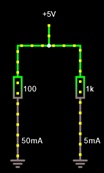
Adjust the voltage slider to 5V (right hand window).
Ensure left resistor = 100 Ω, right resistor = 1 Ωk
To change: Right click on the right resistor when it turns blue, and hit edit in pop up window. Change the resistance value as required.
a) What is the total current flowing from the 5V source?
b) Are the resistors in series or parallel?
c) Use Ohm's laws to determine the effective resistance of a single resistor that could replace the two resistors and not affect the current flow
d) What do you notice about the value of the equivalentresistance compared to R1 and R2
Question 2 Voltage divider
Take the circuit you have built for Task 1
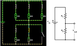
You will delete all the components in the left hand side and add a second resistor to the right hand arm. This makes a voltage divider. Its value should default to 1kOhm. Your circuit will look like this and is electrically equivalent to the circuit shown on the right. We'll call the top resistor R1 and the bottom resistor R2.
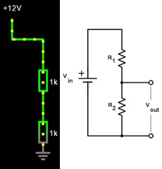
To calculate the voltage over R2, we can use the voltage divider formula Vout= Vin (R2/(R1 + R2)
a) Measure and record the voltage drop over and current through each resistance of 1 kOhm (R1 and R2)
b) Use the voltage divider formula to calculate the voltage over R1 and R2
c) Change R2 to 11 kOhm. Measure and record the voltage drop over and current through each resistance (R1 and R2)
d) Use the voltage divider formula to calculate the voltage over R1 and R2
Question 3 Wheatstone Bridge
Open Circuits > Other Passive Circuits > Wheatstone Bridge
In this section, we will combine two voltage dividers into a Wheatstone Bridge:
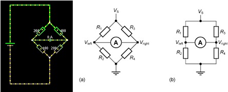
Adjust R4 in small steps (e.g., 0.05 ?) away from the value of 200 ? to about 200.3 ?.
Note the current in the galvanometer arm. Remember most galvanometers have a FSD of 20 ?A.
a) Build a table of values below and plot a graph:
b) Comment on the relationship of the galvo current to the value of R4
When the bridge is not balanced, adjust the value of R2 to null the current in the bridge (make current zero)
c) Record all the values of the resistors and check that the values of resistance satisfy the voltage divider relationship i.e., R2/R1 = R4/R3
d) Hover you cursor over point A and check the voltage you have calculated
Question 4: Series and parallel resistances
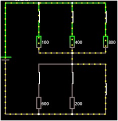
Open Circuits > Basics > Resistors
First close all open switches by clicking on them.
Press run.
a) Why is the current passing only through the wire in lower parallel resistance?
Bringing the cursors over each resistor in turn (100, 400 and 800) will give you information about voltages and current for each of the resistors.
b) What do you notice about the voltage drop over the 100, 400 and 800 ? resistances in the upper parallel combination?
c) Calculate the equivalent resistance of the upper parallel connection of resistors
d) How much current flows into the equivalent resistor?
e) Calculate the current following through each the 100, 400 and 800 ? resistors
f) Work out the power dissipated in each resistor
P=I2R
|
|
100 Ω
|
400 Ω
|
800 Ω
|
|
voltage
|
|
|
|
|
Current
|
|
|
|
|
Power
|
|
|
|
g) Sum the power dissipation
h) Use P=VI to calculate power deliver by battery
Now open the switch in the lower parallel circuit ie..remove the wire from the circuit:
i) Calculate the voltage drop measured across each of the two parallel circuits and ground. i.e., treat as voltage divider. To do this, you need to condense the circuit into two equivalent resistances in series and use voltage divider formula
Vout= Vin (R2/(R1 + R2)