Reference no: EM132722798
KB7001 Computational Fluid Dynamics and Heat Transfer - Northumbria University
Assignment - Design and validation of a heat sink
Assignment Brief - Design and validation of a heat sink
Problem Statement
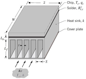
An isothermal silicon chip of W = A mm and Z = B mm is soldered to a heat sink of equivalent size and generates heat at a rate of qc = C W (total), as shown in Figure 1. The heat sink needs to be designed so that the chip's temperature Tc remains below 80 0C when the ambient temperature is 30 0C.
The heat sink has a base thickness of Lb = D mm and an array of rectangular fins, each of length Lf. Airflow at T = 30°C is maintained through channels formed by the fins and a cover plate, and for a convection coefficient of h = E W/m2.K, a minimum fin spacing of 3 mm is dictated by limitations on the flow pressure drop. The solder joint has a thermal contact resistance of R"t,c = F m2 . K/W.
Design constraints
1. The maximum height of the fins Lf should not exceed 80 mm.
2. The minimum thickness of any fin is 2 mm
3. The minimum distance between any two fins is 3 mm
4. Material data is given in the table.
Part 1. Two-dimensional heat sink analysis using numerical finite-difference method
Using information provided in the "Problem Statement" section, "Design constraints" section and in "Parameters" table, determine the following:
1. Taking advantage of symmetry, discretise the heat sink geometry and write 2-dimensional finite- difference equations for each node.
2. Rewrite the equations of (1) in Gauss-Seidel form.
3. Determine the 2-dimensional temperature distribution in the heat sink using Gauss-Seidel method. Continue iterations until the node temperature difference between final iteration and previous iteration is less than 0.2°C.
4. Determine the total heat loss per heat sink length.
Part 2. Three-dimensional heat sink analysis using analytical method and ANSYS numerical method
As an engineer assigned this task and using information provided in the "Problem Statement" section, "Design constraints" section and in "Parameters" table, determine the following:
Develop at least 3 different designs and evaluate their performances and cost for each design. For material selection, you can refer to the Table "Material data". For the final selected design you must investigate how changes in both the fin length and the convective heat transfer coefficient affect the heat transfer rate in the heat sink, and which parameter (h or Lf) has a greater effect on performance of the heat sink.
Using analytical method
1. Include the details of the model and analytical equations you have used to evaluate three different heat sink designs. Each design must have different fin cross sections.
2. Any assumptions you have made must be stated.
3. Select the final heat sink design and justify why this design was selected.
4. For selected final design, perform Parametric Study and investigate the effect of varying convection coefficient (h) and fin length (Lf) on heat transfer and justify your results.
Using ANSYS numerical method
5. Construct the CAD models of heat sinks for all three designs with structured hexahedral mesh only and determine and plot the temperature distribution and heat transfer rate in the sink using ANSYS Steady- State Thermal module.
6. Compare heat sink analytical results with ANSYS results and provide detail discussions, justifications and conclusions. You should compare three different cross section shapes (one cross section per design).
Your Part 2 of the assignment must include (as minimum) the following sections: Problem Statement
Design 1
- Description (including diagrams)
- Analysis
- Discussion of Performance
. . . (repeat the above for each three designs)
Part 3. Combined fluid flow and heat transfer analysis of the heat sink
Using the same configuration of the heat sink shown in Figure 1, and assuming that constant qc enters the heat sink, and also using information provided in the "Problem Statement" section, "Design constraints" section and in "Parameters" table, determine the following:
Using analytical method
1. Assuming that flow is fully developed, determine Reynolds number and flow velocity.
2. Demonstrate whether the flow is laminar or turbulent and determine hydrodynamic and thermal entry lengths.
3. Determine the mean outlet temperature of air.
Using ANSYS CFD method
4. Create 3-D heat sink model with structured hexahedral mesh only.
5. Conduct three-dimensional CFD analysis for the heat sink using ANSYS Fluent for the same conditions as those for analytical method.
6. Refine your model mesh (double the number of elements) and run mesh sensitivity analysis to demonstrate that there is no effect of mesh on the results.
7. Using ANSYS Fluent, demonstrate the effect of fin spacing on flow pressure drop.
8. Compare analytical and numerical (CFD) results for temperature, velocity, pressure, heat flux, and provide detail discussions, justifications, and conclusions.
9. Plot distributions of velocity, temperature, pressure and heat flux in the heat sink and channels.
10. If the air flow velocity increases 30% and heat transfer rate qc increases 20%, redesign the heat sink to maintain the chip's temperature Tc ≤ 80 0C at minimum heat sink cost.
Attachment:- Design and validation of a heat sink.rar