Reference no: EM132856695
ISE 375-L Facilities Design, University of Southern California
Please read the instruction CAREFULLY. There are six questions in this homework set. On your submission, please show all your work.
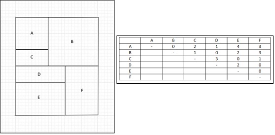
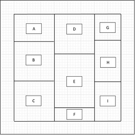
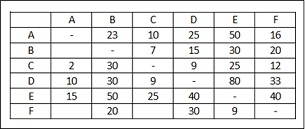
Question 1. Consider CRAFT. Using the diagram and the flow matrix (fij) given below, determine Dij and also find the total cost of all departments. (Assume Cij = 1)
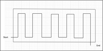
Question 2. Consider seven departments (labeled A through G) with the following area requirements: A = 5 grids, B = 6 grids, C = 2 grids, D = 3 grids, E = 9 grids, F = 7 grids, and G = 8 grids. Using the spacefilling curve shown below, show the layout that would be obtained from the sequence B-E- A-C-F-G-D.
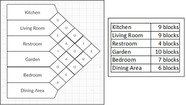
Question 3. A construction company is trying to develop a layout for a house. The total space available is 45 grids (9x5). Given the area requirement and activity relationship chart below, develop a block layout and calculate the adjacency score using the assumptions provided.
a. Assumption 1: The minimum acceptance limit is E
b. Assumption 2: 3 Blocks of sweep width is equal to 1 band width
c. Assumption 3: Bedroom (B) is important, so that will be the first department selected.
d. Assumption 4: The flow pattern of the layout will start from top left corner and end in top right corner and the travel path is wave-like, as discussed in lecture.
e. Adjacency score: A -> 10, E -> 5, I -> 2, O -> 1, U -> 0, X -> -10
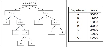
Question 4 There is a vacant building which measures 700' x 300' in length and width. Suppose the first cut is a horizontal cut, and departments B, E, and G are assigned to its top while the remaining departments (A, C, D, and F) are assigned to the bottom. The area requirements for each department are given below. Using the cut-tree diagram, develop a block layout while calculating the length and width of each department.
f. Notation: h denotes horizontal cut and v denotes vertical cut.
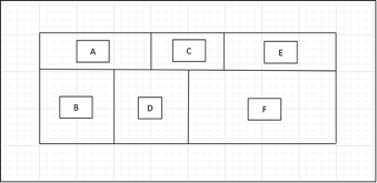
Question 5 Given the initial layout below, use the horizontal serpentine pattern to build a new layout using MCRAFT. The number of bands is 4.
Question 6 Using BLOCPLAN, convert the following from-to-chart to a relationship chart. With the relationship chart and given layout, compute the "efficiency rating" and determine the REL-DIST score. Each grid represents a unit square and the following scoring cost vector is being used: A = 10, E = 5, I = 2, O = 1, and U = 0, and X = -10.
Attachment:- Facilities Design.rar