Investigate the operation of automatic reset circuits

Assignment Help Electrical Engineering
Reference no: EM131304845

OBJECTIVES:

The objectives of this experiment are:

1) To investigate the operation of automatic reset circuits.
2) To understand the difference between a positive edge triggered, negative edge triggered, and a level triggered flip-flop.

PROCEDURE 1: Automatic reset circuits

Many times, it is desirable to reset the JK flip-flops when the power is first turned on. To reset a JK flip-flop it is necessary to momentarily connect the CLR input to logic 0. After a few microseconds, the CLR input can then go to logic 1 and the JK flip-flop can be operated in synchronous mode. To accomplish this we may use an RC circuit. Initially the capacitor is discharged. When the power (VCC) is applied to the circuit, it causes the capacitor to charge to VCC through the resistor. Remember that in a "series RC circuit", the capacitor is considered fully charged after 5 time constants (t = 5RC). When the power is turned on, the CLR input of the JK flip-flop will receive a logic 0 and then as the capacitor charges up, the CLR terminal will be pulled up to +5V after a delay of 5 time constants.

a) Construct the circuit as shown in Figure 1.

1700_Figure1.jpg

2223_Figure2.jpg

Fig. 1 Automatic reset of a 74LS76 JK flip flop

b) Set switches A and C to logic 1 and switch D to logic 0. Connect the pulser to switch X for normally high (normally high means the switch is in the up position), then toggle the switch downward and next, up again.

c) This should cause the LED monitor to turn on indicating that the output Q of the flip-flop is at logic 1.

d) Turn the power supply OFF and then ON. You should observe that the output Q of the flip- flop is reset to logic 0. Repeat this procedure at least 3 times, and each time you should observe that the output of the flip-flop is reset to logic 0.

PROCEDURE 2: Positive edge triggered, negative edge triggered, and level triggered flip-flops.

a) Construct the circuit as shown in Figure 2.

1303_Figure3.jpg

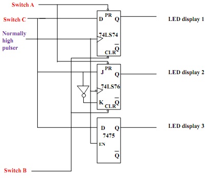
Fig. 2 Circuit to test the differences between the 74LS74, 74LS76, and 7475 flip-flops

b) To turn on LED displays 1 and 2, set switch A to logic 0 and switch B to logic 1. Check your circuit if all three LED displays stay off. Press (toggle down) and release (toggle up) the normally high pulser (e.g., switch X on the trainer board). Do the outputs of the first 2 flip- flops change?

c) While keeping switch A at logic 0 and switch B at logic 1, set switch C to logic 1 then to logic 0. Are there any changes in the states of the first two outputs (LED 1 and LED 2)? Why?

I got to know more about the ICs 74LS76 and 74LS74 by changing logic of the switches

d) Repeat steps a) and b), but this time switch A should be set to logic 1 and switch B should be set to logic 0. Are there any changes in the states of the first two outputs (LED 1 and LED 2)? Why?

e) Now set switch A and switch B both to logic 1. Fill in the following table:

Switch A

Switch B

Switch C

The Pulser

LED 1

LED 2

LED 3

1

1

0

Up Position


1

1

0

Down position


1

1

1

Up Position


1

1

1

Down position


f) With the pulser high (X switch is up), change the state of switch C from logic 1 to logic 0 and then back to logic 1. What do you observe?

Repeat Step f with the pulser is low. What do you observe?

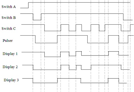
Complete the following timing diagram:

439_Figure.jpg

Reference no: EM131304845

Questions Cloud

Name three types of transmission impairment : Distinguish between baseband transmission and broadband transmission.
Provide one specific example of an online nursing education : Provide one specific example of an online nursing education resource or application that the master's prepared nurse would recommend to classmates who are pursuing an advanced role
Can we say whether a signal is periodic or nonperiodic : Can we say whether a signal is periodic or nonperiodic by just looking at its frequency domain plot? How?
What is the solution or recommendations for port of hueneme : Restricted amount of space for expansion (Abier). What is the solution or recommendations for the Port of Hueneme? What are the bottlenecks of Port Hueneme?
Investigate the operation of automatic reset circuits : To investigate the operation of automatic reset circuits - To understand the difference between a positive edge triggered, negative edge triggered, and a level triggered flip-flop.
Which component of the total delay is dominant : The length of the link is 2000 Km. The speed of light inside the link is 2 × 10⁸ m/s. The link has a bandwidth of 5 Mbps. Which component of the total delay is dominant? Which one is negligible?
How long does it take to download this file using a 56-kbps : A computer monitor has a resolution of 1200 by 1000 pixels. If each pixel uses 1024 colors, how many bits are needed to send the complete contents of a screen?
Design all members of the 6 span truss each span : Design all members of the 6 span truss each span is 12 ft long, the height of the truss is 16 feet shown if w = 10,000 pounds. The allowable maximum tensile stress P/A is 1000 psi where P is the force in the member and A is the cross sectional are..
Draw the bandwidth : A periodic composite signal with a bandwidth of 2000 Hz is composed of two sine waves. The first one has a frequency of 100 Hz with a maximum amplitude of 20 V; the second one has a maximum amplitude of 5 V. Draw the bandwidth.

Reviews

Write a Review

Electrical Engineering Questions & Answers

  Lithium ion battery technology

The paper includes Lithium ion battery technology with its advantages and disadvantages. The paper discusses about the Lithium air battery in which detailed reactions of Lithium with air including nonaqueous as well as aqueous are given.

  Power transformers and tariffs

Construction of different types of power transformer, significant energy savings

  Paper on orthogonal frequency-division multiplexing

This document is shown a paper on Orthogonal frequency-division multiplexing with advantages, disadvantages and uses.

  Function of the hmi in a scada system

This assignment contains electronics engineering questions like State the commonly found components of a SCADA (Supervisory control and data acquisition) system. and decribe the function of the HMI in a SCADA system.

  Resultant waveform of the odd harmonic series

Prepare an Excel graph showing the individual components and summated resultant waveform of the odd harmonic series resulting in an approximate square wave.

  Explain scada system

Explain the function of the HMI in a SCADA system.

  Design a 2-digit 24 second shot-clock

Design a 2-digit 24 second "shot-clock" countdown timer with pushbutton controller.

  Model a discrete-time system

To understand di erent signal models To be able to model a discrete-time system and design simple signal processing algorithms.

  Draw a relay construction diagram

Draw a relay construction diagram and briefly explain the operation of a relay.

  Frequency division multiplexing

Write a short technical report on Frequency Division Multiplexing

  Impact of electron energy

Briefly discuss the impact of electron energy, electron current and target on the Bremsstrahlung generated.

  Traffic light controller

The schematic of the traffic light controller

Free Assignment Quote

Assured A++ Grade

Get guaranteed satisfaction & time on delivery in every assignment order you paid with us! We ensure premium quality solution document along with free turntin report!

All rights reserved! Copyrights ©2019-2020 ExpertsMind IT Educational Pvt Ltd