Reference no: EM13501762
Question One
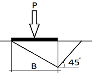
Show that the ultimate load for a strip footing under long-term conditions using the two triangle failure surfaces shown in Figure As 1 is Pu = 1/2 γB2Nγ, where

Question Two
a) What are the two principle factors influencing the allowable bearing pressure in the design of a specific footing? Are both of these factors equally important? Are both factors likely to be equally relevant for different soils types?
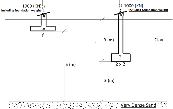
b) The foundation in the Figure As 2 is to support a factory which is to contain some precision machinery. The locations of the rigid footings are given because of an adjacent ramp system for service tunnels. The whole structure, including floor slabs, live and dead loads are to be γ supported on the column, the design load for each column being 1000 KN. The majority of this load will be applied on the installation of the machinery. One item of machinery, and indeed the first to be installed consists of delicate conveyer system which will reach between the columns. It is stated by the manufacturer that this conveyor system will not operate if there is more than 5 (mm) change in level between the ends of the system. Given that the minimum footing size is 2(m) x 2 (m), design the foundation so that the conveyor system experiences continued operation.
Question Three
a) A new building is to be built on a series of spread foundations that will be undrained by saturated clay. Undisturbed soil samples have been obtained from this site and are ready to be tested. Should the laboratory test programme focus on producing values of c' and Ø', or Su
(undrained shear strength)? Explain.
B) A grain silo, which is very heavy structure, was recently built on saturated clay. Because the harvest season was fairly short and intense, the silo was completely loaded fairly quickly (i.e., within a couple of weeks). This is the first time the silo has been loaded. The grain weights about twice as much as the empty silo. The weight of this grain, along with the weight of the silo, has induced both compressive and shears stresses in the soil below.
Suddenly, someone has become concerned that the soil may be about to fail in shear under the weight of the silo and grain. This is a legitimate concern, because such failures have occurred before. Discuss the soil mechanics aspects of this situation and determine whether the risk of failure in the soil is increasing, decreasing, or remain constant with time.
Question Four
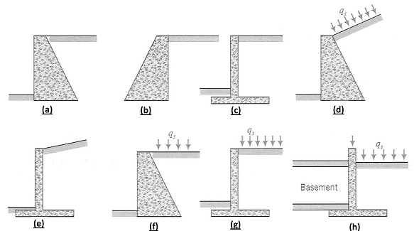
Figure As 1 shows rigid walls of height Ho with different geometries. Sketch the distribution of lateral earth pressures on each wall; indicate the location and direction of the resultant lateral force. Show on your diagram what other forces act on the wall, for example, the weight of the wall (Ww) and the weight of the soil (Ws). You should consider two cases of soil-wall friction: (1) Type equation here. δ > 0 and (2) δ = 0.
Question Five
Which of the two walls in Figure As 1 gives the large horizontal force? Show your calculations).

Question Six
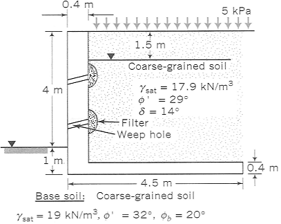
The drainage system of a cantilever wall shown in Figure As 1 became blocked after a heavy rainstorm and the groundwater level, which was originally below the base, rose to1.5 (m) below the surface. Determine the stability of the wall before and after the rainfall. Neglect seepage effects.
Question Seven
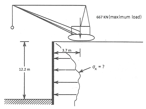
Calculate the additional stress (as a function of depth) that a temporary construction wall , like that shown in Figure As 1, must take as the result of a crane sustained in the zone above it.
Question Eight
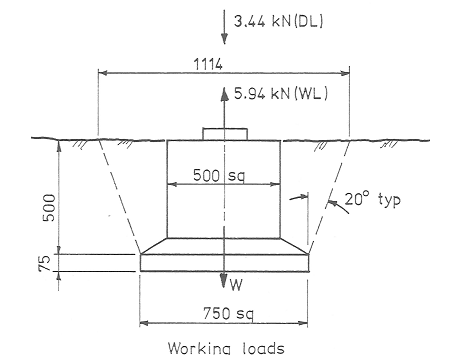
A large carport has footing loading as shown on Figure As 1 when normal maximum wind force id applied.
a) Using the stability formula specified chapter two of the lecture notes. Determine the total weight W required (this include the weight of soil). Soil density = 19 KK/m3.
b) Determine the minimum weight of concrete. This should be at least = WL↑ + 0.8 DL↓ /0.8.
c) Calculate the actual weight of concrete.
d) Find the total weight mobilised, i.e. Concrete + soil.
