Reference no: EM133048260
ENGT5155 Digital Manufacturing - De Montfort University
Assignment: Design and manufacturing of quadcopter using principles of digital manufacturing
Learning outcome 1: Understand the different processes of product development through digital manufacturing
Learning outcome 2: Ability to use design optimization techniques using appropriate software for digital manufacturing
Learning outcome 3: Ability to generate machine codes for 3D printing machines
Learning outcome 4: Understand the application of automation in digital manufacturing
Preparation of report - please read carefully:
Part 1: Introduction
Provide a suitable background and discuss the following that can be used for the development of the quadcopter (model provided in the last page of this document) through digital manufacturing.
- Computer aided Design/Engineering
- Topology optimization (pros and cons)
- Hierarchy diagram for manufacturing processes.
- Manufacturing support system/s.
- Design / draw a layout of material handling systems.
Part 2: Design optimization of quadcopter body:
This is an individual activity to optimize the body through topology optimization feature in ANSYS Workbench. Show your steps with figures and appropriate reasoning. Compare the topology optimized part with the original design.
Some advice and considerations:
- You'll be using PLA filaments as material for this part. The material properties of you'll need for the design include Yong's (elastic) modulus of 3500MPa, Poisson's ratio of 0.35, ultimate strength of 65MPa and density of 1.24 gr/cm3.
- Design the quadcopter body for a total lifting load of 1kg.
- To save computational cost, you can optimize only a quarter of the quadcopter frame (only one arm) as it is a symmetrical body. Then generate the full design after optimizing one arm through mirroring or reparative pattern in ANSYS Space Claim.
- You can use both Density-based (SIMP) and Level-set method for topology optimization. However, your final design should be at a final stage ready for 3D printing, i.e. you'll need to do any post-processing required such as smoothing using ANSYS Space Claim or any similar software before finalizing your design
- You'll also need to demonstrate validity/optimality of your design through an appropriate method/reasoning.
- Note that in the next task, the optimized part will not be printed as solid, but an infill density of 5-30% will be applied in 3D printing the optimized body.
Part 3: FDM process for 3D printer quadcopter parts:
Part (a): quadcopter body
- Proceed with your selected design to prepare the G-code for 3D printing throughs FDM process.
- Generate G-code for 3D printing the body using Prusa Slicer software (check that the machine settings in the software match the Prusa printer you are going to book in Workshop). Show a figure of the final sliced part including support structures in your report. With appropriate reasoning, explain why you have chosen these settings.
- Important considerations before generating the slices for G-code: an appropriate print orientation, minimum support structures, appropriate infill density, minimum print time, ...
- Carefully choose an in-fill density between 5-30% considering stress levels in the optimized body.
- Book one of the four Prusa 3D printers located in workshop and start 3D printing the quadcopter body. If you cannot complete the print by end of the first day, you'll need to pause the print at end of the day and resume it on the next day.
- After the print, complete any required post-processing, e.g. remove support structures etc.
- Show figures from different stages of the print in your report including a screenshot of the sliced model and a screenshot of the Sliced Info which shows print time and cost. Explain any change you could make on the print settings if you were going to start a new print of the same part.
Part (b): Additional parts for 3D printing through FDM
- Import the STL files of the camera gimbal arms, dampers and link connectors (10 parts in total), four motor mounts and four propellers, all together into the Prusa Slicer software. Consider slice thickness of 0.15mm and solid in-fill (100%density). Arrange the parts in appropriate location and orientation.
- Show figures of the final sliced model including support structures. The figures should show the arrangements of the parts within printer build environment. Explain the reason for your choice of part arrangement.
- Show a screenshot of Sliced Info (bottom right corner of the screen when sliced model is generated which shows print time, material usage, cost ...).
- State and explain pros and cons of FDM process for manufacturing these parts.
Note: you don't need to 3D print the parts related to part (b).
Part 4: Re-design the landing pad using lattice structure infill:
- Use ANSYS Space Claim or any appropriate similar software to re-design the landing pad by applying lattice structure in-fill.
- Justify your choice of lattice structure in-fill, density/thickness and any other design considerations related to this task including an appropriate manufacturing process you would
recommend.
- Include pros and cons of your recommended process for manufacturing the lattice landing pad.
Part 5: Alternative processes for fabrication of quadcopter parts:
Part (a): Additive Manufacturing processes
In addition to the material extrusion (e.g. FDM), there are many other processes for additive manufacturing which can be classified into 7 main processes (refer to relevant lecture slides). Explain which other processes can be used for fabrication of the quadcopter parts designed/presented in sections 2-4. Consider different factors such as choice of material, size, resolution, cost, design complexity and support structure requirement, etc. include pros and cons of each process.
Part (b): Subtractive manufacturing and net shape manufacturing
Comment on the suitability of subtractive manufacturing and net shape manufacturing for the fabrication of the presented quadcopter parts. Include pros and cons of the methods in relation to the parts.
Part 6: CNC G-code generation:
This task involves drilling holes on the camera gimbal arm-1 through CNC end milling process and you are required to write down a suitable G-code with the following specifications. In addition to your G-code, you need to show a screenshot of the G-code simulation in an appropriate software (you are advised to use NCviewer, but you can also use other online tools such as Easel, jscut).
- Define the homing process
- Define the diameter of the tool required for this operation
- Define appropriate depth of cut in steps
- Comment on the fixture required for this operation
- Provide a copy of your G-code as well as a screenshot of the software simulation in your coursework
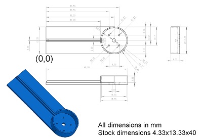
Figure 1- camera gimbal arm-1
Part 7: 2D cutting optimization/Nesting:
Import (provided on Blackboard) the files of the Battery and electronic equipment box parts 1,2 and 3 as well as camera gimbal mounting plates parts 1&2 (there should be 5 parts in total which can be organized to optimize their cutting plan together/simultaneously) in any appropriate CAD software that can be used to draw and export 2D drawings e.g. AutoCAD, Solidworks, Space Claim (ANSYS) etc. assume all parts will be cut from same material with same thickness of 1.0mm. Stock material dimensions would be 290x210 mm. Apply 2D Nesting on the 2D parts and explain the reason for your choice of parts arrangement for 2D cutting. Show figures of the final drawings and optimized model (appropriate cutting plans). Find the total rectangular area required to extract given parts based on your optimized cutting plan.
Part 8: Automation:
State and explain the different types of automated manufacturing processes for the parts selected in sections 2-7 that includes:
- Digital assembly practices its types e.g. Assembly line, conveyor belts to streamline the digital manufacturing process. Organize the assembly process in clear steps and show appropriate plan, layouts or diagrams.
- Apply cellular and group technology on the digital manufacturing processes to improve productivity.
- Assign each part of the quadcopter with appropriate AIDC (Automatic identification and data capture) for automated assembly which should include a unique code e.g. QR code, BAR code etc. and Alpha-Numeric Code for each part.
Part 9: Sustainable manufacturing and AI:
(a) State and explain the sustainable manufacturing processes for the parts presented in sections 2-7.
Briefly comment on the sustainable manufacturing and its significance these days. Identify and justify the manufacturing processes which are sustainable and comment on why sustainable manufacturing is preferred over normal/conventional manufacturing.
(b) Artificial Intelligence (AI)
State and explain the role of artificial intelligence in the digital manufacturing processes. Identify and assign to the presented quadcopter parts, design, manufacturing, and assembly processes in which AI can play an important role.
Explain how we can use AI in quality assurance of the manufactured/assembled quadcopter.
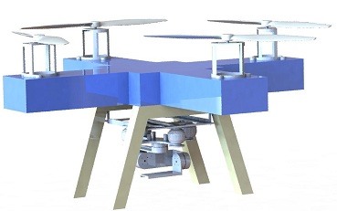
Figure 2. Assembeled quadcopter
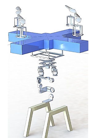
Figure 3. Exploded view of the quadcopter
Attachment:- Digital Manufacturing.rar