Reference no: EM13857649
1. Calculate the frequency for each of the following periods:
a. 1 s
b. 0.2 s
c. 50 ms
d. 1 ms
e. 500 ms
f. 10 ms
2. A sine wave goes through 5 cycles in 10 ms. What is its period?
3. For a particular 0° reference sinusoidal current, the peak value is 100 mA. Determine the instantaneous value at each of the following points:
a. 35o
b. 95o
c. 190o
d. 215o
e. 275o
f. 360o
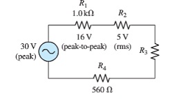
4. Determine the rms voltage across R? in the following figure.
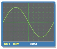
5. Determine the rms value and the frequency of the sine wave displayed on the scope screen in the following figure.
6. a. Find the capacitance when Q = 50 mC and V = 10 V.
b. Find the charge when C = 0.001 mF and V = 1 kV.
c. Find the voltage when Q = 2 mC and C = 200 μF.
d. Find the capacitance when Q = 50 mC and V = 10 V.
7. Convert the following values from picofarads to microfarads:
a. 1000 pF
b. 3500 pF
c. 250 pF
8. A student decides to construct a capacitor using two conducting plates 30 cm on a side. He separates the plates with a paper dielectric (er = 2.5) that is 8 x 10⁻⁵ m thick. What is the capacitance of his capacitor?
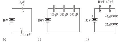
9. Find the total capacitance for each circuit in the following figure.
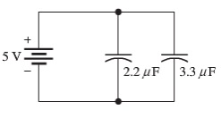
10. Determine the total capacitance and total charge on the capacitors in the following figure.
11. Determine the time constant for each of the following series RC combinations:
a. R = 100 Ω, C = 1 μF
b. R = 10 MΩ, C = 56 pF
c. R = 4.7 kΩ, C = 0.0047 μF
d. R = 1.5 MΩ, C = 0.01 μF
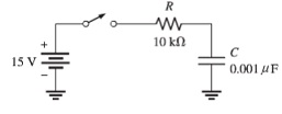
12. In the circuit of the following figure, the capacitor is uncharged initially. Determine the capacitor voltage at the following times after the switch is closed:
a. 10 μs
b. 20 μs
c. 30 μs
d. 40 μs
e. 50 μs
13. Ideally, what should the reactance of a bypass capacitor be in order to eliminate a 10 kHz ac voltage at a given point in an amplifier circuit?
14. An 8 kHz sinusoidal voltage is applied to a series RC circuit. What is the frequency of the voltage across the resistor? Across the capacitor?
15. Find the impedance of each circuit in the following figure.
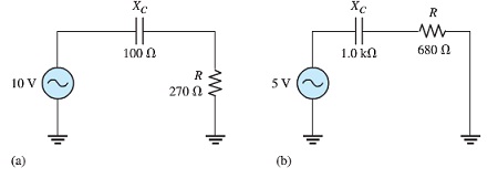
16. Calculate the total current in each circuit of the figure in question no. 15.
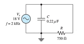
17. Determine the impedance and the phase angle in the following figure.
18. For the parallel circuit in the following figure, find each branch current and the total current. What is the phase angle between the source voltage and the total current?

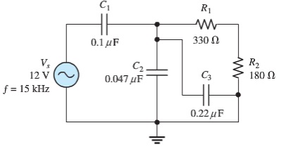
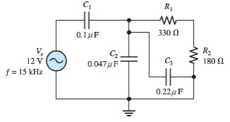
19. The circuit in the following figure is a complex circuit consisting of five components. With trigonometry, it can be shown that R1, R2, C2, and C3 are equivalent to a resistance of 3.08 V in series with a capacitive reactance of 39.5 V. From this given information, determine the voltages across each component in the original circuit.
20. Find the current through each branch and the total current in the following figure.
Attachment:- exercise5.1.pdf