Reference no: EM133677517
Numerical Analysis
Question 1a
Figure Q1a shows the forces acting on the aircraft during a climb performance.
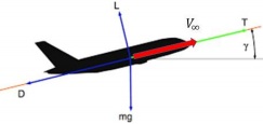
Figure Q1a
The governing equation is given by
Rate of Climb = dh/dt = T-D/W.V∞
Assume that the aircraft is climbing at a constant speed of V∞ = 150 m/s
If the mass of the aircraft is 50,000 kg, the thrust T and drag D varies with altitude h, with the following relations:
T = 119770 - 11.15 h
D = 52890 - 4.3977 h + 0.001 h2
Question 1a (i)
Formulate a numerical procedure to calculate the aircraft climb performance using the forward difference method (i.e. to find a numerical expression for h at different t).
Question 1a(ii)
Based on the numerical method formulated in Question 1a(i), compute the aircraft altitude at different time, using Δt = 60 s where the initial height is 500 m. (Hint: complete the following table.)
Time (s) Aircraft altitude h (m)
0 500
60
120
180
Question 1a(iii)
Analyse the accuracy and efficiency of the numerical formulation used by commenting the effect of dt on the accuracy and efficiency of the algorithm.
Question 1b
Appraise THREE (3) possible methods that can be used to verify and validate the result of your computation.
Question 2a
Given the following system of equations:
15x1 - x2 + 2x3 = 12
3x1 + 8x2 - 2x3 = -25
x1 + x2 + 10x3 = 6
Using the following initial guess, calculate the solution by Gauss Seidel method.

Present your result at each iteration.
Question 2b
An propeller powered aircraft is flying at altitude of 1000 m, the level flight power required of the aircraft is given by the following equation:
PR = 4.25 V3 - 1050.2 V2 + 140000V + 460 W
Note that W in the above equation denotes the unit of power calculated by using velocity V in the unit of m/s. The maximum engine power is 10,000 kW. Use the initial guess to formulate a computation procedure to compute the maximum speed of the aircraft using Newton's Raphson method. The accuracy should be up to 1 decimal point in m/s.
Question 2c
A rectangular wing having a constant chord length. Its half wing span-wise distribution of sectional lift coefficient is given as follow via Table Q2c and Figure Q2c:
y (m) Cl
0.0000 0.3785026
0.8518 0.3770185
1.6826 0.3723656
2.4720 0.3638927
3.2005 0.3503956
3.8502 0.3299093
4.4051 0.2550066
5.1785 0.1918889
5.3780 0.1062034
Table Q2c
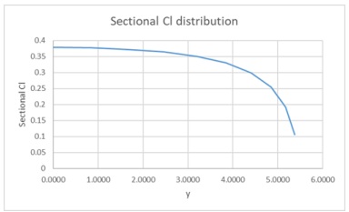
Figure Q2c
Use the trapezoidal rule to design and compose a computational step to calculate the total lift coefficient of the wing.
Question 3
Consider a one-dimensional system of length L. The following partial differential equation describes the diffusion and convection phenomena that is taking place in the system.
∂u/∂t + ∂/∂x (cu + μ∂u/∂x) = 0
Where c and μ are constants, and the boundary condition is given by u (x = 0) = 1, u(x = L) = 0
Consider a cell center finite volume discretization as shown below:
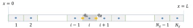
Where q is the flux.
Question 3a
Formulate a control volume and explicit time numerical scheme to discretize the governing equation, by re-writing the governing equation into 1-D convective differential form, and prove that the flux is given by:
q = cu + μ.∂u/∂x
Question 3b
Compose the discretized expression for Right-Hand and Left-Hand Fluxes, qR, and qL.
Question 3c
Design and express the numerical scheme using Explicit Scheme.
Question 3d
Appraise the accuracy of the numerical scheme in terms of spatial and temporal accuracy.
Question 3e
Analyse the appropriate stability criteria for the numerical method proposed.
Question 3f
Design a suitable way to model the boundary condition at and .
Question 3g
Compute the boundary condition at x = 0 and x = L.
Question 4
The load acting over the span of the aircraft horizontal stabiliser is uniformly distributed as shown in Figure Q4.
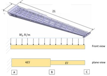
Figure Q4
The span of the horizontal stabiliser is , and the uniformly distributed load is W0 N/m. The stabiliser can be considered to be fixed supported at the root. The horizontal stabiliser is approximated using a 2 element beam bending model. Both element has a length of, and the element cross sectional property is shown in the figure.
Question 4a
Calculate the equivalent loads acting at nodes A, B and C, respectively.
Question 4b
The element stiffness matrix for beam element is given as follow:
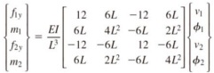
Analyse and compute the stiffness matrix for each of the beam element.
Question 4c
Formulate and assemble the stiffness matrix of the entire horizontal stabiliser.
Question 4d
State the boundary conditions for this model.
Question 4e
Design a suitable numerical procedure for the solution for the deflection and rotation at node C. (Note: just provide the procedure, NO actual working is required.)