Reference no: EM132411641 , Length: 2 pages
AM modulation and demodulation
Question 1
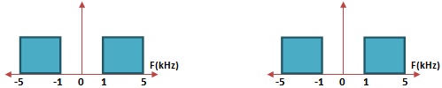
We have to wirelessly transmit two baseband signals whose spectrum is identical and is shown below.
The devices available in the storage room are: i) Ideal Low-pass Filters, ii) DSB-SC Modulators, iii) Carrier generator with adjustable frequencies, iv) Adder circuit (Summing Amplifier).
a) Using the devices available as mentioned, formulate a mechanism to modulate the baseband signals such that the modulated signal spectrum lies between 9kHz and 21kHz. Draw a block diagram using above mentioned components and explain the effect on signal on each stage. State all the adjustable parameters for the components used. For example, cutoff frequency of Low-pass Filter and Frequencies of the Carrier Generator.
b) Using the devices available as mentioned, formulate a mechanism to recover the baseband signals from the modulated signal in part (a). Again, draw a block diagram with above mentioned components and explain the procedure step by step. State all the adjustable parameters for the components used. For example, cutoff frequency of Low-pass Filter and Frequencies of the Carrier Generator.
Question 2
There are 5 baseband signals whose identical frequency spectrum is given as
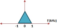
Requirements
1) Transmit modulated signal containing all 5 baseband signals
2) No interference between each signal
3) Bandwidth of Modulated signal should not exceed 5.75kHz
4) All 5 Baseband signals should be recoverable from the transmitted modulated signals
Come up with an AMPLITUDE Modulation and Demodulation scheme that satisfies all above requirements.Explain the modulation and demodulation scheme with block diagram while stating signal at each point. Select and mention an appropriate carrier frequencies and filters as required. Draw the frequency response of the filters used if they are other than standard LPF, BPF and HPF.