Reference no: EM133654688
Sensors and Sensing for Scientists
Assignment 1: Electronic basics, Ohms Law
Question 1: Calculating Resistance: An Automobile Headlight
What is the resistance of an automobile headlight through which 2.50 A flows when 12.0 V is applied to it?
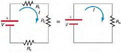
Question 2: Calculating Resistance, Current, Voltage Drop, and Power Dissipation: Analysis of Series Circuit
Suppose the voltage output of the battery in Figure is 12.0 V , and the resistances are R1 = 1.00 Ω, R2 = 6.00 Ω, and R3 = 13.0 Ω.
(a) What is the total resistance?
(b) Find the current.
(c) Calculate the voltage drop in each resistor, and show these add to equal the voltage output of the source.
(d) Calculate the power dissipated by each resistor.
(e) Find the power output of the source, and show that it equals the total power dissipated by the resistors.
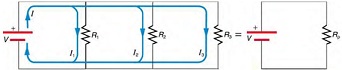
Question 3: Calculating Resistance, Current, Power Dissipation, and Power Output Analysis of a Parallel Circuit
Let the voltage output of the battery and resistances in the parallel connection in Figure be the same as the previously considered series connection: V = 12.0 V , R1 = 1.00 Ω, R2 = 6.00 Ω, and R3 = 13.0 Ω.
(a) What is the totalresistance?
(b) Find the total current.
(c) Calculate the currents in each resistor, and show these add to equal the total current output of the source.
(d) Calculate the power dissipated by each resistor.
(e) Find the power output of the source, and show that it equals the total power dissipated by the resistors.
Question 4: Calculating Resistance, IR Drop, Current, and Power Dissipation: Combining Series and Parallel Circuits
Figure shows the resistors from the previous two examples wired in a different way-a combination of series and parallel.
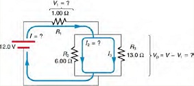
We can consider R1 to be the resistance of wires leading to R2 and R3.
(a) Find the total resistance.
(b) What isthe IR drop in R1?
(c) Find the current /2 through R2.
(d) What power is dissipated by R2?
Question 5: A negative temperature coefficient (NTC) thermistor has a resistance that depends on temperature i.e., R =f(T). The higher the temperature, the lower the resistance. The transfer function shown allows us to map resistance to temperature and vice versa.
A thermistor is placed into the circuit below. This circuit is called a voltage divider - it does just that, divides the input voltage up depending on the values of the two resistances in the divider.
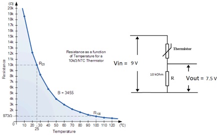
A voltage of 7.5 V is measured over the 10 k? resistor. Use Ohms law to determine the current through this resistor.
Determine the current running through the thermistor. Give your reasoning.
Using the principal that the supply voltage has been divided across thermistor and the fixed 10 k? resistor, what is the voltage drop over the thermistor?
Now knowing the voltage and current for the thermistor, calculate its resistance and use the transfer function to determine the temperature.