Reference no: EM132563391
Question 1
Each of the four vertical links connecting the two rigid horizontal members is made of steel and has a uniform rectangular cross section of 10 x 40 mm.
Two loads, 24-kN each, are applied as shown to the horizontal member EFG.
The four pins at B, E, C, and F have the same diameter d and are made also of steel.
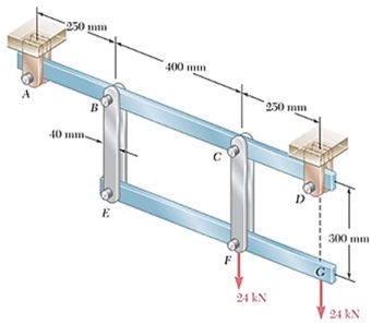
Find the permissible values of the diameter d of the pins, knowing that the allowable values of the normal, shearing, and bearing stresses for the steel used are, respectively, 180 MPa, 120 MPa, and 230 MPa. Consider:
(i) the maximum value of the average normal stress in the links.
(ii) the average shearing stress in pins.
(iii) the average bearing stress in the links.
b) Determine the stresses (i), (ii), and (iii) in each link for the diameter selected.
c) Determine the deflection of point E, point F, and point G.
Question 2
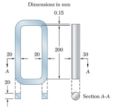
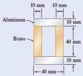
An aluminum link (Ea = 70 GPa, αa = 23.6 × 10⁻⁶/°C) and a steel rod (Es × 200 GPa, αa = 11.7 × 10⁻⁶/°C) have the dimensions shown at a temperature of 20°C. The steel rod is cooled until it can be fitted freely into the link. The temperature of the whole assembly is then raised to 40°C. Determine the final normal stress (a) in the rod, (b) in the link. (c) the final length of the rod.
Question 3
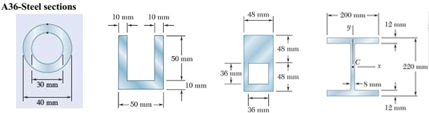
Two vertical forces are applied to a beam as shown in the figure. The cross section for the beam is still undecided. The possible options are shown below.
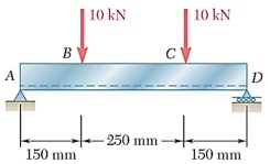
Determine the maximum tensile and compressive stresses in the beam when using the different cross section options described below. Compare stresses with the material yield stress listed in Appendix B.
|
|
Aluminum
|
Brass
|
|
Modulus of elasticity
|
70 GPa
|
105 GPa
|
|
Allowable stress
|
100 MPa
|
160 MPa
|
Question 4
Two W6 x 12 rolled sections are welded together as shown. Knowing that for the steel alloy used σU = 58 ksi and using a factor of safety of 2.0, determine the largest tensile load that can be applied at the lower corner (point A).
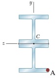
Consider axial loading plus bending effects.