Reference no: EM132222676
Aerodynamics Homework - Elementary Aerodynamics
PROBLEM 1 -
A conventional wind turbine extracts power from wind flow by retarding the oncoming flow. This is called the flow retardation or induction, where the induction factor is normally represented by a. In other words, if the freestream velocity is represented by v∞, the flow velocity in the vicinity of the turbine becomes v∞(1 - a), where a > 0.
The induction factor generally depends on the aerodynamic characteristics of the blades, e.g. the lift and drag coefficients, the tip-speed ratio and solidity factor of the turbine. The tip-speed ratio for any section of the blade may be defined as the ratio of the tangential speed (due to rotation) and the freestream velocity, i.e. λ = rω/v∞; r and ω being the radial distance of the section from the axis of rotation and the rotational speed, respectively. The solidity factor for any section of the blade may be defined as σ = Nc/2πr, where N is the number of blades, and c = c(r) is the local chord length -the blade of the turbine is normally tapered.
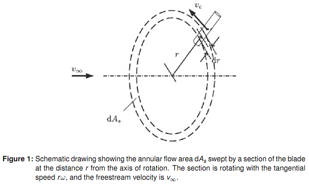
According to the blade element momentum theory, the total axial force (i.e. in the direction of the main flow) acting on each section of the blades is equal to the axial force acting on the corresponding annular element of the flow. This is mathematically represented as
½ρV2relNcxdAb = ½ρv2∞4a(1 - a)dAs, (1)
where Vrel is the relative velocity between flow and the moving airfoil section, cx is the axial aerodynamic force coefficient; also, dAb and dAs are the differential planform area of a single blade and the annular flow area, respectively (see Figure 1).
The axial aerodynamic force coefficient may be written as
cx = clcos φ + cd sin φ, (2)
where φ = α + θ; α and θ being the angle of attack and the blade local twist angle, respectively.
Using data given in Table 1, find the local axial induction factor, lift and drag coefficients, and the angle of attack for a section with λ = 4, σ = 0.04 and θ = 0. It is assumed that the lift and drag coefficients are not sensitive to the Reynolds number, Re, for the flow regime considered here.
|
Table 1: Lift and drag coefficients of a high aspect ratio wing with the Clark Y airfoil section as a function of angle of attack at Re ≈ 6 x 10⁶ (Silverstein, 1935).
|
|
α (degrees)
|
cl
|
cd
|
|
-8.1
|
-0.2
|
0.0124
|
|
-6.7
|
-0.1
|
0.0097
|
|
-5.3
|
0.0
|
0.0086
|
|
-3.9
|
0.1
|
0.0089
|
|
-2.6
|
0.2
|
0.0106
|
|
-1.2
|
0.3
|
0.0139
|
|
0.2
|
0.4
|
0.0181
|
|
1.5
|
0.5
|
0.0234
|
|
2.8
|
0.6
|
0.0305
|
|
4.2
|
0.7
|
0.0382
|
|
5.6
|
0.8
|
0.0476
|
|
6.9
|
0.9
|
0.0581
|
|
8.4
|
1.0
|
0.0696
|
|
9.8
|
1.1
|
0.0836
|
|
11.3
|
1.2
|
0.0999
|
|
12.9
|
1.3
|
0.1170
|
|
14.7
|
1.4
|
0.1380
|
|
16.7
|
1.51
|
0.1660
|
|
17.3
|
1.4
|
0.1910
|
|
19.2
|
1.3
|
0.2570
|
|
22.0
|
1.2
|
0.3150
|
PROBLEM 2 -
Describe the phenomena called "dynamic stall", and explain its main features.
PROBLEM 3 -
If V is the flow velocity vector and ∇ is the gradient operator, show that the following equation holds in the cylindrical coordinate system:
∇ · V = 1/r ∂/∂r(rVr ) + 1/r ∂Vθ/∂θ + ∂Vz/∂z. (3)
REFERENCES - Abe Silverstein. Scale effect on Clark Y airfoil characteristics from NACA full-scale wind-tunnel tests. National Advisory Committee for Aeronautics, Rep. No. 502, 1935.