Reference no: EM131800263
Principles of Fluid Flow
Question 1 - Water Flowing out of an Axisymmetric Tank
Water flows out a small circular hole (A0) at the bottom of an axi-symmetric tank. The radius (r), of the tank increases with elevation (h) above the bottom of the tank Both h and r vary with time t. There is no inflow to the tank - only an outflow. See Figure 1.

Figure 1: Axisymmetric tank (with horizontal sections which are circular). The outflow is from the tank bottom.
The volume of water in the tank (∀) and the relation between depth of water in the tank (h) and the radius (r) is given by:
∀ = 2/3 (Πr2)h
h = kr4
where... k = 78.60 m-3
(a constant)
A0 = 4.0 cm2
Cd = 1.0
Initially (t = 0), the depth of water is ho = 2.0 m. Complete the following:
(a) Show that for this axi-symmetric tank d∀/dh = Aplan = Πr2.
(Hint: You need to take into account the fact that h and r are related.)
(b) Find an expression for the variation of water depth in the tank with time.
(c) How long will it take for the tank to empty?
(d) Find an expression for the variation of the flow rate (Q) from the tank with time. What is the initial flow rate from the tank? What is the flow rate from the tank when the depth of water is h = 1.0 m ?
Question 2 - 2D Free Surface Flow followed by Flow through a Nozzle
Water flows down an open channel and on through a nozzle at the downstream end. At upstream Section 1, the depth is y1 = 1.5 m and the flow velocity ui is unknown but uniform through the depth (i.e. constant through the water column at Section 1). The streamlines at Section 1 are straight and parallel.
The channel terminates in a streamlined nozzle through which the water flows and is discharged into the atmosphere. Section 2 is at the end of the nozzle. The vertical dimension of the nozzle is 0.6 m, the bottom of the nozzle is 0.3 m above the channel bed and the top of the nozzle is 0.9 m above the channel bed. See Figure 2. With the flow being in the vertical plane, you need only consider unit width (into the page). You may assume negligible energy losses between the two sections.

Figure 2: Free surface flow down a channel and on through a nozzle. A representative streamline has been drawn between the two sections.
Complete the following:
(a) Find an expression for the velocity 'a at elevation z above the channel bed at Section 2. Your expression for u will be in terms of the unknown, uniform velocity ui and z.
(b) Find an expression (involving an integral) for the flow per unit width, q (m2/s) through the 2D nozzle at Section 2.
(Hint: Similar problems: See Example 1 in the Lecture Energy Part 2 and Tutorial Question 1 in the Energy Part 2 Lecture.)
(c) Determine the flow velocity ui to the nearest (cm/s).
Question 3 - Average Flow Velocity and Momentum Fluxes in a Pipe with Turbulent Flow
Water enters a pipe at Section 1 with a uniform velocity over the cross-section of the pipe. Section 2 is some distance downstream where the velocity distribution has stabilised and no longer changes; this is referred to as ' established' flow. (See Figure 3. This velocity distribution for turbulent flow (requiring the Reynolds number IR = u¯D/v > 4000 for pipe flow) is approximated by:
u/Uc = (1 - r/R)1/n
where..., u = velocity at distance r from the pipe centreline
Uc = velocity along the pipe centreline
r = distance from the pipe centreline
R = radius of the pipe = D/2
For many practical flows (with IR ≈ 50,000 - 300,000), the one seventh power law is used with n = 7 (Reference: Figure 8.17 in Fundamentals of Fluid Flow, B. R. Munson, D. F. Young and T. H. Okiishi, 5th edition, 2006, John Wiley and Sons, Inc., ISBN 0 471 67582 2.) (You will learn more about the power law for turbulent velocity distributions in the later topic of boundary layers in this course.)
However, the actual value of n is dependent upon the Reynolds number IR = u¯D/v and for IR ≈ uD/UcRe, 106, a better value is n = 9. The velocity distribution with n = 9 is what will be used in this question.
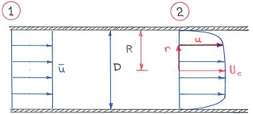
Figure 3: Uniform flow at Section 1 and established turbulent flow at Section 2.
Complete the following with n = 9 in equation (3):
(a) Find an expression for the cross-sectionally averaged flow velocity (u¯) in terms of the cen¬treline velocity Uc, (for established flow) where Q = Au¯ = ∫A u.dA and dA = 2Πr.dr and A = ΠR2.
(b) Find an expression for the momentum flux (M) past a pipe cross-section in terms of p, Q, u¯ when the turbulent flow has been established. In other words, find the value of the constant k in M· = kρQu¯.
(c) Write down the momentum equation for the water in the control volume between Sections 1 and 2. Include a representation for the pressure and shear forces acting on the water in a control volume between Sections 1 and 2. Considering whether M·1 > M·2 or M·1 < M·2, briefly explain what is happening in terms of the pressure and shear forces which act on the fluid in the control volume, where M·1 and M·2 represent the momentum fluxes at Sections 1 and 2 respectively.
Question 4: An Inclined Slot Jet Entering an Open Channel
An inclined jet of water (angle not specified), issues from a nozzle with a rectangular cross-section with thickness tn, and width B. The velocity of the water leaving the nozzle is un. After emerging from the nozzle, the water free falls from an elevation which is zn above the water surface as shown in Figure 4. The jet of water with velocity uj enters an open channel with a rectangular cross-section of width B at an angle θj to the horizontal (see Figure 4.) The slot jet is directed towards (and not away from) the closed end of the channel. The left hand end of the channel is terminated by a vertical wall.
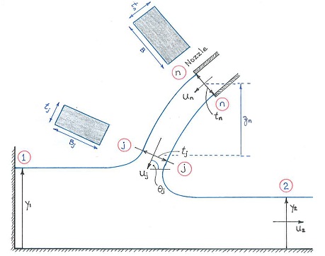
Figure 4: Water exits a nozzle with velocity un and rectangular cross-section (tn x B) at Section n. The water then free falls into an open channel at Section j with velocity uj and rectangular cross-section (tj x Bi). The two rectangular cross-sections, n at the nozzle, and j as the jet enters the channel, are shown shaded in the diagram.
Four sections (1, 2, n, j) are defined (see Figure 4):
- Section 1 is close to the left hand, closed end of the channel. Any velocities near Section 1 can be assumed to be very slow.
- Section 2 is well downstream from where the jet flow enters the channel. The flow at Section 2 is sufficiently distant from the jet that the flow in the channel at Section 2 has settled down and the streamlines there, are horizontal and parallel to the bed.
- Section n is the section at the end of the nozzle.
- Section j is the section through the still free fall jet just before it enters the water in the channel.
In comparison with the hydrostatic forces (acting on the water in the control volume), you may assume negligible shear forces (i.e. negligible friction) along the channel bed.

Figure 5: Abrupt connection between two pipes with different diameters
Data
- Width of the rectangular channel and width of the nozzle is B = 1.0 m.
- Thickness of the nozzle tn = 0.20 m and elevation of the nozzle centreline above the water is in zn= 1.5 m.
- Downwards inclination of the slot jet with respect to the horizontal just before entering the channel is θj = 60 °.
- Flow depths at Sections 1 and 2 are respectively: y1 and y2 = 0.8 m.
- The flow velocity at Section 2 is u2 = 1.25 m/s.
Select and apply the appropriate principles of fluid flow (mass, energy, momentum), to complete the following:
(a) Find the velocity of the water in the jet as it emerges from the nozzle un.
(b) Find both the velocity in the jet uj just before it impinges the water in the open channel. Estimate the corresponding thickness of the jet tj and the width of the jet Bj. You may assume that the relative or percentage change in jet thickness tn, tj and the percentage change in width B → Bj are equal.
(Hint: By analogy, based on continuity, consider why the diameter would change if the jet was an axi-symmetric jet emerging from a circular orifice as it free falls to a lower elevation.)
(c) Only for this sub-question, the data concerning only the jet as it enters the open channel water at Section j, is changed (to render this sub-question independent of the answers from the previous sub-questions) as follows: take uj = 6.0 m/s, θj = 60° Bj = 1.0 m (i.e. same width as the channel width). The data at Section 2 is unchanged (i.e. y2 = 0.8 m, u2 = 1.25 m/s, B =1.0m). Determine both the thickness of the jet tj at Section j, and the upstream depth yi at Section 1.
Question 5: Flow through a Sudden Expansion and Sudden Contraction
Pipe1, a smaller diameter pipe, is connected to a larger diameter pipe, Pipe 2; the connection between the two pipes is abrupt or sudden. Section 1 is located on the smaller diameter Pipe 1 and Section 2 is located on the larger diameter Pipe 2. Both Sections 1 and 2 are located sufficiently far away from the sudden pipe join that any locally generated flow disturbance has negligible effect on the two manometer readings. In other words, the streamlines are straight and parallel to each other at Sections 1 and 2.
There are two parts to this question:
(i) Sudden expansion with the flow from Pipe 1 on the left to Pipe 2 on the right, and
(ii) Sudden contraction with the flow from Pipe 2 on the right to Pipe 1 on the left.
For both cases, irrespective of the flow direction, the positive x-axis is to be taken to be from left to right.
Data for when the flow passes from left to right as well as from right to left
- A1 = 1 m2 (cross-sectional area of smaller diameter pipe)
- A2 = 3 m2 (cross-sectional area of larger diameter pipe)
- u1 = 3 m/s (velocity magnitude in smaller diameter pipe)
- Manometer reading at Section 1 is 0.55 m.
Sudden Flow Expansion
The flow is from the smaller diameter Pipe 1 with cross-sectional area A1 through a sudden expansion to the larger diameter Pipe 2 with area A2.
Complete the following:
(a) Find u2.
(b) Find the manometer reading at Section 2.
(Hint: See Tutorial Question 2 in Momentum Part 2 for a realistic analytical expression for the head loss associated with a sudden expansion.)
(c) Find the force (f→x) and its direction, exerted by the water on the pipe expansion
Sudden Flow Contraction
The flow is now from right to left in Figure 5, that is, from Pipe 2 and Section 2 to Pipe 1 and Section 1. The data under Figure 5 is still relevant for this flow case i.e. same manometer reading of 0.55 m at Section 1, same flow velocities at the two sections except that they are now from right to left, and the x-direction from left to right is retained.
Data on the head loss coefficient (KL) for a sudden contraction from a large pipe to a small pipe are determined experimentally and can be found in Table 1.
|
Asmall/Alarge
|
0
|
0.1
|
0.2
|
0.3
|
0.4
|
0.5
|
0.6
|
0.7
|
0.8
|
0.9
|
1.0
|
|
KL
|
0.50
|
0.46
|
0.41
|
0.36
|
0.30
|
0.24
|
0.18
|
0.12
|
0.06
|
0.02
|
0
|
Table 1: Head loss coefficient KL for sudden contractions where HL = KL (u2small/2g) and usmall = flow velocity in the smaller pipe.)
Complete the following:
(d) Find the manometer reading at Section 2.
(e) Find the force (f x) and its direction, exerted by the water on the pipe contraction.
(Hint: Take great care with the signs for the vector quantities in the momentum equation.)