Reference no: EM133050525
Engineering Materials and Materials Selection
Learning outcome 1: Able to communicate effectively on material selection with material scientists.
Learning outcome 2: Able to understand the implications of different modes of material failure.
Learning outcome 3: To understand the effects of composition and heat treatment on the properties of different types of material.
Learning outcome 4: To select materials to minimise the likelihood of component failure.
QUESTION 1
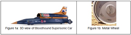
The Bloodhound Supersonic Car (Figure 1a) is a land vehicle that is being designed to achieve 1000 MPH and break the current speed record. The design of the wheels is not easy, they need to withstand the enormous centrifugal forces turning at very high speed. A normal racing car wheel will just burst. The approach is to make them of a solid machined metal (Figure 1b).
The stress in the rotating wheel is given by:
σ = ρR_2ω2
Where ρ is the density, R is the radius of the wheel and ω is the angular velocity.
a) Show that given a traveling speed (1000 MPH = 447 m/s) the maximum stress of the wheel does not depend on the radius of the wheel. Explain why.
b) Derive a material index for the selection of a material for this application. Use suitable mechanical properties to do so. The table catalogues the requirements.
c) Select graphically the material in the suitable graph.
QUESTION 2
The Strait of Gibraltar crossing is a hypothetical bridge or tunnel spanning the Strait of Gibraltar (about 14 km or 9 miles at its narrowest point) that would connect Europe and Africa. There have been many studies about the feasibility and cost of the tunnel since 1979. In 2021 the UK, Spain and Morocco have announced plans to return to the project (Figure 2).
You are requested to select a material for the walls of the tunnel following the method that we have seen in the lectures. It is going to be built with a tunnel boring machine. It is surrounded by high pressure deposits. It needs to withstand an external pressure without failure. It also needs to be as cheap as possible since the main burden is the cost of the infrastructure.
You need to follow the selection of materials process seen in the lectures and you will need to define constraints, free variables, objective, function... Note that not everything is given in the text above and you will need to make your own documented decisions.
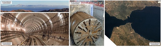
Figure 2: (a) view toward Gibraltar, (b) undersea rail tunnel, (c) tunnel digger, (d) satellite view of potential Gibraltar crossing
You have to document the whole selection process.
(a) Using the above information and your own assumption (if applicable), translate the problem
(b) From your translation, derive the performance index.
[Hint] Pending on your own assumptions, you may have more than one performance index
(c) Use Granta Edupack 2021 software to create a graph representing the material index and identify the region of the chart with the cheapest materials for the tunnel.
[Hint] Pending on your own assumptions, you may have more than one performance index
(d) Select one of the suitable material highlighted in you material selection and compare your material choice with actual materials used in similar tunnels.
QUESTION 3
A crack with a depth of 2 cm is found in a cast iron rod of an old steam engine. Every weekend the machine is used for 8 hours for demonstration purposes, during which it is run at 15 rpm and the load in the rod varies from +6.4×10⁴ N to -6.4×10⁴ N. It may be assumed that the crack is completely closed under compressive load but that under tensile load crack closure is negligible. The Paris relation is sufficiently accurate until failure.
To answer the following questions, you have been given the following: Kc = 16 MPa m0.5 ΔKth = 5
MPa m0.5 cross section rod = 0.04 m2 factor in the Paris relation: C = 4.3×10⁻⁸ m(MPam0.5)-4 KI = 1.12 σ (πa)0.5
a) Using the above information, justify if it is safe to use this machine for demonstrations and if so for how long?
b) If the load varies from +0.92 MN to -0.92 MN, would it be safe to use the machine and for how long
QUESTION 4
a) Using appropriate drawings, examples and references justify the following statement: " Creep mechanism "bulk diffusion" is highly dependent with stress".
b) Using appropriate drawings, examples and references justify the following statement: "Creep mechanism "bulk diffusion" is highly dependent on grain size".
c) Using suitable examples and references explain what mechanism of creep can be prevented using a single crystal part.
d) Using suitable examples and references explain what mechanism of creep can be accentuated with alloying elements.
QUESTION 5
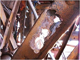
Blackpool Tower has developed problems of corrosion as seen in Figure 3. The corroded parts must de replaced by new parts made of the same material as the original parts.
Suggest two strategies that can be used to prevent or reduce the corrosion of Blackpool Tower after the replacement of the corroded components.. You need to justify your choice with examples and discuss their advantages and disadvantages.
QUESTION 6
a) Modern bicycle frames are made with aluminium ALU 6061, which tend to crack after years of use. Whereas steel frames may last decades and never fail. Contrast the behaviour of aluminium versus steel subjected to many cycles of stress.
b) Using the information seen in class and suitable examples or references, contrast Aluminium grade 6061T0 with Aluminium grade 6061T6
c) Explain the process to transform Aluminium 6061T0 into aluminium 6061T6
d) Bike users, often ask ,if their cracked aluminium frames can be repaired. Commonly, cracks appear on the weldments (Figure 4). Peter suggested that it would be easy to weld again by grinding the crack, expose new base material and weld again on the new material. However, Peter's approach is never advised. Discuss one reason why this is advised against from the structural point of view.
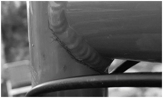
Figure 4: Cracks located along weld.
e) Aluminium grade 6061 T6 is shown in Figure 5, indicate three features that are clearly seen in the picture.
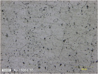
Figure 5: Metallography of aluminium grade 606 T6
f) Make a drawing of the microstructure of aluminium of the previous question after being subjected to a heat treatment to reach microstructural phase equilibrium.
QUESTION 7
A forklift (Figure 6) has failed. Some researchers have investigated the root cause of the failure and presented the outcome of the investigation in a research article.
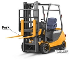
Figure 6: Forklift
George Pantazopoulos, Athanasios Vazdirvanidis, Andreas Rikos, Anagnostis Toulfatzis, Analysis of abnormal fatigue failure of forklift forks,
Case Studies in Engineering Failure Analysis, Volume 2, Issue 1, 2014, Pages 9-14, ISSN 2213-2902,
Although the alloy of the fork is heat treatable as stated clearly in the article,
"the forks are made of a common structural steel grade 34Cr4 (W.Nr. 1.7033), see Table 1 [5]. This steel grade is a heat treatable alloy commonly used as a machine element in axle and shaft fabrication."
the authors do not include the heat treatment as one of the recommendations given in the "Conclusions and recommended actions". Discuss why the authors do not recommend the heat treatment and justify your answer with relevant data.
MP2714 Computer Aided Design and Simulation
Assignment 1 - Centrifugal Clutch Design
The aim of this assignment is to use industrial CAD systems to solve an engineering design problem.
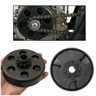
Figure 1 Centrifugal Clutch
Usinga range of CAD and Simulation toolsyou are to design a Centrifugal Clutch. The assessment will be based on a Design Report highlighting your design work and use of CAD to solve an engineering problem.
The report will contain the following elements:
• Analysing Hardware requirements for CAD
• 3D CAD Modelling
• 2D Drawings for Manufacture
• FEA Analysis of a Clutch Shoe
• Motion Analysis of the Clutch
This is an individual assignment; you are to design a suitable centrifugal clutch to match a specific engine. An engine specification will be given to you and will be different for each student.
Learning Outcome 1: Analyse and compare the hardware requirements of different CAD systems. Identify and distinguish between the different types of CAD software: 2D draughting, 3D modelling (wire-frame, surface, solid), and other relevant systems
Learning Outcome 2: Use industrial standard CAD systems to produce the following: 3D CAD models, 2D engineering drawings.
Learning Outcome 3: Use industrial standard CAD and FEA systems to solve engineering design problems.
Learning Outcome 4: Analyse and model engineering situations using ordinary differential equations and solve ODEs.
Learning Outcome 5: Solve mathematical models of physical systems using simulation methods.
Technical Requirements
• The clutch must be designed to fit the Power-Take-Off shaft (PTO).
• The clutch must not engage when the engine is at idle (below 1500 rpm unless stated otherwise in the engine specification)
• The engagement of the clutch should be gradual from just above idle rpm up to the rpm at the start of the recommended operating speed range of the engine
• Clutch should remain engaged over the full operating speed range of the engine
• Clutch must not slip at peak torque.
• Drive from the clutch must be a single sprocket to take astandard roller chain suitable for the Horsepower and max rpm of the engine.
Engine Specifications
An engine specification will be given to you from the range of small Honda Engines. (do not choose your own)The Honda GX GC or GS engine range is a popular range of engines for a wide range of applications and it is common to use Centrifugal Clutches on these engines.
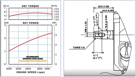
Each engine specification contains Performance Curves for information on Power, Torque and Engine Speed (rpm) as well as Technical Drawings of the PTO shaft. (Power Take-off shaft). Samples are shown below - Note: your engine specification may be different to these.
Sample Performance Curves Sample Drawing of a PTO Shaft
Design Report
You will be assessed via a Design Report. The report should be a 2000 word, liberally illustrated Technical Report. Most of the content is expected to be detailed Screen Shots/Imagesof your design. Graphical Results of your Motion Simulations are also expected. The report should also include initial design concepts and calculations related to the design.
It should be written in 3rd person, past tense with a logical numbered Chapter system. Research used for Part 1 should be correctly referenced.
Report Structure:
1. Analyse and compare the hardware requirements of different CAD systems. Identify and distinguish between the different types of CAD software: 2D draughting, 3D modelling (wire-frame, surface, solid), and other relevant systems
(a) Research typical CAD/PC systems used currently in industry. Consider PC / Hardware requirements for different CAD systems (include Processor/s, Monitors, Graphics Cards, Digitisers, RAM, Print/Plot devices). Describe how these might be configured in a typical Design Office.
(b) Show examples of the different types of CAD used in industry, include examples of 2D Drawing, 3D Solid Modelling, 3D Wire-Frame/Surface Modelling and any other relevant systems. Do not include vendor names of software i.e. SolidWorks, Catia, AutoCAD. Focus on the different types of CAD software that is available.
2. Use industrial standard CAD systems to produce the following: 3D CAD models, 2D engineering drawings.
With appropriate Screenshots and Descriptions show 3D Models and 2D Drawings of your design with descriptions to
(a) 3D CAD Part Models of Clutch Design
(b) 3D Assembly of Clutch Design
(c) 2D Detail Drawings of parts to be Manufactured i.e. Drum, Shoes, Backplate etc. (do not include standard parts i.e. nuts, bolts, springs, fasteners etc.)
3. Use industrial standard CAD and FEA systems to solve engineering design problems.
(a) Initial design calculations to predict behaviour of clutch design and establish boundary conditions.
(b) FEA Simulation of Clutch Shoe under maximum load conditions
(c) Motion Analysis of Clutch to show engagement.
Attachment:- Centrifugal Clutch Design.rar
Attachment:- Engineering Materials and Materials Selection.rar