Explain how you could measure the ripple frequency

Assignment Help Other Engineering
Reference no: EM131738099

Lab Assignment: Bridge Rectifier

Introduction:

Lab is based on the previous lab on half-wave and full-wave rectifiers and taking that knowledge to build a bridge rectifier.

Materials and Equipment:

Materials:

• Simulated Parts (Multisim):

o 10:1 transformer (To access in Multisim under Master Database, in Group > Basic > Transformer > Select 1P1S)
o Two diodes 1N4001
o Two 2.2 kΩ resistors
o One 100 μF, 50 V electrolytic capacitor (any voltage rating is fine since is simulation only)
o One fuse (any rating is fine since is simulation only)

Equipment:

• Virtual Instruments (Multisim):

o Tektronix Oscilloscope
o Agilent Multimeter

• AC Power Source (To access in Multisim under Master Database > Group > Sources > Power Sources > AC_POWER)

Note: Multisim must be configured so a date and time stamp is visible in all simulations. Omission of the date and time stamp causes the lab to be worth only 1%. Please refer to the Procedure to view date and time stamp at the end of the lab.

1. Construct the bridge rectifier circuit shown in Figure 1. Double click the AC_POWER SOURCE and set the voltage value to 30Vrms. Notice that no terminal of the transformer secondary is at ground potential (some simulation software will not run if it is not connected to the ground, check yours). The input voltage to the bridge, VSEC, is not referenced to ground. Be sure to set the tolerance of the resistors to 10%. (Refer to the Tools and Templates section if you do not know how to set tolerances for resistors.)

2. Using the AC Power Source to provide VAC, run the simulation.

3. Use the Agilent multimeter to measure VSEC (rms) and then use the oscilloscope to measure the peak output voltage (VLOAD) without a filter capacitor. Be sure to take screenshots of your measurements showing the equipment, the circuit, the connections to the multimeter, and the date and time stamp.

4. Tabulate all data gathered.
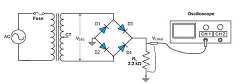
1841_Rectifier-Circuit.jpg
Figure 1

4. Connect the 100 μF capacitor in parallel with the load resistor. Measure VLOAD, the peak-to-peak ripple voltage VRIPPLE, and the ripple frequency. Tabulate all data gathered and compare the results with and without the filter capacitor.

Without the capacitor With the capacitor
Output load voltage VLOAD
Peak-to-peak ripple voltage VRIPPLE
Ripple frequency

5. Choose a diode among the four connected to the bridge and open it. Simulate an open diode in the bridge and explain what happens to the output voltage, the ripple voltage and the ripple frequency?

6. Investigate the effect of the load resistor on the ripple voltage by connecting a second 2.2 kΩ, 10% tolerance, and load resistor in parallel with RL and C1 in the full-wave circuit of Figure 3. Measure the ripple voltage. Be sure to capture the screenshots for the circuit and measured values with the date and time stamp (see procedure below). When taking screenshots of your measurements, make sure that the circuit is also visible with connections to the equipment. Multiple screenshots may be necessary to demonstrate the circuit setup and the measurements.

Review questions:

1. Explain how you could measure the ripple frequency to determine if a diode were open in a bridge rectifier circuit.

2. What is the maximum dc voltage you could expect to obtain from a transformer with a 3 Vrms secondary using a bridge circuit with a filter capacitor?

Deliverables:

1. Follow the template "Lab Report Template" to compile the report, and make sure to check the report against the grading rubric below. The template can be found in the "Tools and Templates" link in the left navigation panel. The template should provide places for you to include the analysis of the circuit/calculations, table, screenshots of the circuit and measurements, and the answer to the questions. Again, be sure the screenshots of the circuit and measurements, including the date and time stamp.

2. Make sure to include the table, calculations, screenshots of the measurements and the answer to the questions. Save the document as Lab2YourGID.docx (ex: Lab3G00000000.docx).

Procedure to view date and time stamp:

On the upper menu of Multisim, click "VIEW" then click "SPREADSHEET VIEW", click the "SIMULATION" tab on the bottom left of the screen. You will see the screen below with a date and time stamp of your simulation with the circuit design you created.

938_Circuit.jpg

Attachment:- Lab-Report-Template.rar

Reference no: EM131738099

Questions Cloud

Decision tree methodology with net present value methodology : Decision tree methodology with net present value methodology determine Expected Profit of two years of operations where warehouse space is leased on spot market
Celebrity endorsement-who would your choice of celebrity be : Celebrity Endorsement-Who would your choice of celebrity be, and why? “How” would you employ them?
It is challenging task and involves five steps : Mr. Rockness trains college professors. It is a challenging task and involves five steps.
Three assumptions underlying pay-for-performance plans : This chapter identifies three assumptions underlying pay-for-performance plans.
Explain how you could measure the ripple frequency : Explain how you could measure the ripple frequency to determine if a diode were open in a bridge rectifier circuit.
Compare the calculated and measured values in the table : Compare the calculated and measured values in the table and analyze the performance of the transistor. Discuss whether the values are the same or different.
Find the voltage across the given resistor : Find the voltage across the resistor R3. Find the total impedance ZT. Calculate the voltage V2 and the current IL. Find the power factor of the network.
Assess the appropriate dsm diagnoses for mark : What are the significant diagnostic markers ("red flags") that indicate acute alcohol withdrawal syndrome for Mark?
Write about an opposition to your topic specifically : Write about an opposition to your topic specifically. Do not just write about an opposition to your topic's branch.

Reviews

Write a Review

Other Engineering Questions & Answers

  Explain lzss compression and what are the improvements of

Explain LZSS compression and what are the improvements of LZSS on LZ77

  What class of polymers have a melting temperature

Name three parameters that must be reported along with experimental data of stiffness and strength of PMC.- What class of polymers have a melting temperature?

  What do you expect the slew rate of this amplifier to be

A two-stage CMOS op amp has each of its first-stage transistors Q1 and Q2 operating at an overdrive voltage of 0.2 V. The op amp has a uniform -20-dB/decade frequency response with a unity-gain frequency of 100 MHz. What do you expect the slew rat..

  Kinds of transistor circuits amplifying and switching

1. The bridge rectifier is similar to a full-wave rectifier .because it produces a full-wave output voltage.

  Plot the bod remaining in the water

CEE 357 Winter 2014, HW#5, How much HOCl is needed to react with each mg/L of S in the latter reaction? Plot the BOD remaining in the water

  Intended to design and implement a logic circuit

It is intended to design and implement a logic circuit for managing the places in a parking lot, disposed in a straight line, that meets the following specifications:

  Provide your position on whether residential sprinklers

Residential sprinklers have been debated between the fire officials and builders for a very long time. There are many documented studies that indicate residential sprinklers, along with smoke detection systems, should be the first line of defense ..

  Centralized database system for the system

Centralized database system for the system to easily handle all of the information and availability of the system at all times and from all the places to make sure that the system developed is of complete utility for the users.

  Review gartner groups hype cycle for emerging technologies

Review the Gartner Groups hype cycle for emerging technologies.

  Determine the total line inductance

Determine the total line inductance in mH/m - Given the operating frequency to be 60 Hz, find the total inductive reactance of the line in Ω/km and in Ω/mi.

  Find natural frequencies and mode shape vectors for truss

Find the natural frequencies and mode shape vectors for the truss using one bar element for each link. Show all work involving the assembly of the load vector and characteristic matrix.

  Draw sketches of all the re-designed parts

HEADSTOCK DRIVE - Locate the incorrect design areas of the Headstock Drive and replace them with the correct design.

Free Assignment Quote

Assured A++ Grade

Get guaranteed satisfaction & time on delivery in every assignment order you paid with us! We ensure premium quality solution document along with free turntin report!

All rights reserved! Copyrights ©2019-2020 ExpertsMind IT Educational Pvt Ltd