Reference no: EM132834278
ER4200 Advanced Mechatronics - University of Central Lancashire
Learning Outcome 1: Identify and apply a range of engineering solutions to Mechatronics systems
Learning Outcome 2: Critically analyse practical aspects of sensor, actuators, and controllers
Learning Outcome 3: Apply advanced level knowledge and understanding of problems across a wide range of advanced Mechatronics systems
Learning Outcome 4: Apply critical understanding in the devise of an appropriate and effective strategy for processing data; virtual instrumentation and virtual simulation
Task: In the continuous quest of providing professional medical services across the globe, the need for intelligent medical equipment became of great importance to many medical instrumentational manufactures. Smart Surgery Inventions (SSI) is a leading company in the smart robotic arms field that has been utilized in helping the surgeons during their local and remote surgical operations if they are present through the cloud. One of the SSI plans is to upgrade one system's tracking capability to enhance the doctor's experience during navigations to process the patient's tissues. The tracking, in this case, is performed by a photoresistor when exposed to the luminescent.
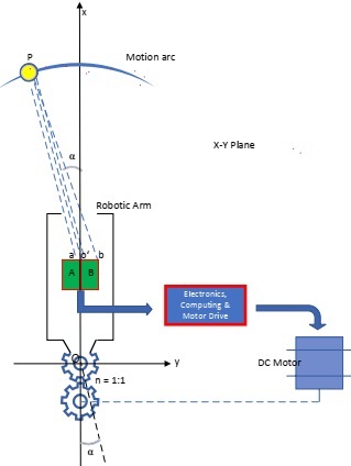
Figure 1. The spotlight tracking mechatronic system
The initial design plan is shown in Figure (1). A specific point (P) on the arc located on the X-Y plane (tissue) that has been identified as malign cells has been illuminated, and the robotic arm should precisely track the light spot with high resolution. For light detection, the system utilizing two photoresistors, A and B. The robot arm must follow the luminescent point P. The difference in the values of the two photoresistors depends on the illuminated areas o'a and o'b.
As a mechatronic engineer in SSI, you have been hired to upgrade the robotic arm with the necessary Electronics, Computing, and Motor drive to provide an integrated solution that encompasses all the requirements for this task. It is essential to notice that the photosensor's resistance is inversely proportional to the values of o'a and o'b.
Figure (2) shows the referencing with respect to the centre of the output Gear and the motor fixed axis. It is known that tan (α) can be approximated to α when α is a small value.
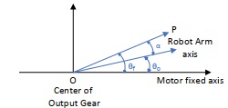
Figure (2): Axis representations with respect to the Motor fixed axis and the origin of the drawing O.
Thus:
o'a = k1 - k2 ∗ tan(α) or RA = R - kα for α>0
and
o'a = k1+ k2 ∗ tan(α) or RB = R + kα for α< 0
For this task, you will need to address the following using referencing whenever required:
1. Propose an upgrade to the mentioned above system using the minimum required components using the necessary Electronics, Computing, and Motor Drive to implement the mechatronic system in Figure (1).
2. Justify your choices for the required components by explaining the operational concept and why your choice fits the system requirements. Use all the necessary equations that describe your choice for:
• Electronics
• Computing
• Motor and Motor Drive
3. Please provide the complete schematic diagram of the system and its corresponding representation in the Simulink or Simscape model where the input is the angle α, and the output is the angular displacement θ.
4. Consolidate your system model using the transfer function reduction technique and simulate the resulting function for small values of -5° < α < 5°.
5. Describe the required software/hardware that you could use to implement cloud computing for remote control operation.
6. Show that different parameter values could change the system response to a sudden input using graphs to show your findings.
7. How can we increase the robotic arm's motion resolution, and how this can be reflected in the system transfer function?
Attachment:- Assignment_20.rar