Reference no: EM132505877
ENSC3004 Solid Mechanics Assignment - The University of Western Australia
Instructions: You need to watch the 3-point bending test of plastic (PVC) beam and the 4-point bending test of mortar beam videos (Assignment folder, LMS). Also you need to use data file according to the student number and answer the questions below.
Part 1 - 3-Point Bending Test
A standard three-point bending test on plastic (PVC) beam follows a procedure stipulated in ASTM D790. This test utilises a three-point loading system as shown in Figure 1. The sample of a rectangular cross-section rests on two supports and is loaded by means of a loading nose midway between the supports. The sample is deflected at a constant strain rate until rupture occurs or until a maximum strain of 5% is reached. Load (P) and displacement are recorded during the test. The sample dimensions are given in Table 1.
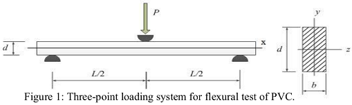
Table 1: PVC Sample Dimensions
|
Support span, L(mm)
|
Width of beam, b(mm)
|
Depth of beam, d(mm)
|
|
60
|
12
|
20
|
Flexural Stress - In the three-point bending test, the flexural stress (σf) is defined as the maximum normal stress (σxx,max) of the test specimen, which can be calculated for any load (P) on the load-deflection curve from the following equation (ASTM D790):
σf = 3PL/2bd2 (1)
Flexural Strain - Flexural Strain (εf) is defined as a nominal fractional change in the length of an element of the outer surface of the test specimen at the midpoint. It may be calculated for any deflection (δ) on the load-deflection curve as (ASTM D790):
εf = 6δd/L2 (2)
Questions -
1. Describe what you observed in the PVC sample in terms of the deformation during the bending test in the video. This should be done in 5 sentences at most.
2. Using the data file given to you, plot the load vs deflection curve for the 3-point bending test of PVC with proper labelling. Determine the maximum load with 3 significant figures.
3. Draw the free body diagram, shear force diagram and bending moment diagram for the PVC sample with the maximum load you found in question 2.
4. Indicate the following with proper drawings for the 3-point bending test:
i) portion of the beam under pure bending if any
ii) portion of the beam under tension
iii) portion of the beam under compression
iv) locations where the beam experiences maximum normal stress, i.e. σxx,max.
5. Compute the maximum normal stress σxx,max when the load is at 5% of strain for the PVC using Equation (1) and (2), comment on the applicability of the equations and any error associated with your computed value.
6. Compare the maximum normal stress you calculated in question 5 with the typical tensile and compressive strengths of PVC in Table 2. Comment on the expected failure mechanism for the 3-point bending test. Compare the expected failure mechanism with the actual failure or deformation of the sample you observed in the video.
Table 2: Typical strength values
|
Material
|
Tensile strength (MPa)
|
Compressive strength (MPa)
|
|
PVC
|
52
|
72
|
Bonus Question - Draw the normal stress distributions (i.e. σxx distribution) in the cross-section at the midspan (2D diagram) with the load at 5% strain for 3-point bending of PVC, assuming the PVC is ideal elastoplastic material.
Part 2 - 4-Point Bending Test
The flexural strength of mortar is determined by standard test methods ASTM C78 (Third-point loading or 4-point bending test). In the four-point loading system schematically shown in Figure 2, the sample of a rectangular cross-section rests on two supports and a half of the load is applied at each third of the span length through a rigid block at the top. The specimen is loaded at constant strain rate until it breaks. Load (P) and displacement of the rigid block are recorded during the test. The sample dimensions are given in Table 3.
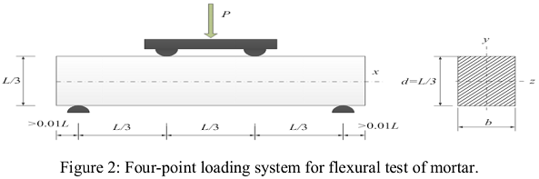
Table 3: Mortar Sample Dimensions
|
Support span, L(mm)
|
Width of beam, b(mm)
|
Depth of beam, d(mm)
|
|
80
|
27
|
27
|
Questions -
1. Describe what you observed in the mortar sample in terms of the deformation during the bending test in the video. This should be done in 5 sentences at most.
2. Using the data file given to you, plot the load vs deflection curve for the 4-point bending test of mortar with proper labelling. Determine the maximum load with 3 significant figures.
3. Draw the free body diagram, shear force diagram and bending moment diagram for the mortar sample with the maximum load you found in question 2.
4. Indicate the following with proper drawings for the 4-point bending test:
v) portion of the beam under pure bending if any
vi) portion of the beam under tension
vii) portion of the beam under compression
viii) locations where the beam experiences maximum normal stress, i.e. σxx,max.
5. Compute the maximum normal stress σxx,max when the load is at the maximum load for the mortar sample.
6. Compare the maximum normal stress you calculated in question 5 with the typical tensile and compressive strengths of mortar in Table 4. Comment on the expected failure mechanism for the 4-point bending test. Compare the expected failure mechanism with the actual failure or deformation of the sample you observed in the video.
Table 4: Typical strength values
|
Material
|
Tensile strength (MPa)
|
Compressive strength (MPa)
|
|
Mortar
|
3
|
45
|
Attachment:- Solid Mechanics Assignment Files.rar