Reference no: EM132383368
ENS3245 Steel Design Project Assignment - Edith Cowan University, Australia
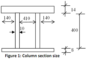
Using the following heavily-welded section fabricated from Grade 300 plates to AS/NZS 3678, as columns in the below portal frame:
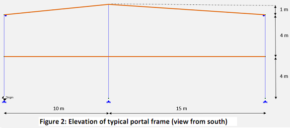
1) Size the floor beams and portal rafters to accommodate the following from both a strength and serviceability (deflection limits) criteria:
- Central portal of 7 portal frames (portals spaced at 8 m centres)
- Roof bracing restrains the top of the upper floor columns in the north-south direction and wall bracing restrains the external columns on both levels in the east-west direction.
- 0.42 BMT Lysaght Trimdek roof and wall sheeting
- Wind loads for a building located on the corner of Joondalup Drive and Grand Boulevard within ECU Student Carpark 2, considering internal pressures for two or three walls permeable and the others (including the west elevation) impermeable. 50-year design life with V500 ultimate wind speed. Determine combinations for wind from the west (from the left hand side of the above elevation) as the critical load case.
- Non-trafficable roof load and floor being used for general office space in the upper floor and office storage space in the lower floor requiring a floor beam depth < 500 mm
- The first floor comprises of 205 deltacore hollowcore planks with a 50 mm structural topping and carpeted finish.
- Both floors have suspended ceilings with lighting and services within the ceiling space with total weight taken as g = 0.2 kPa above the ground floor & g = 0.1 kPa for the 1st floor.
As part of your answer to Q1) provide a tabulated material take-off (weight of structure) divided into weights of each different material type to justify that your design is economical
Show full working for determination of:
a) Design criteria for strength and serviceability referring AS/NZS 1170.0 Tab C1 for deflection limits
b) Applicable loadings and critical combinations
c) Member strength calculations for rafters, beams, columns and any knee/ fly braces used to provide additional restraint - nominate member end fixities considered and reasoning why
d) Serviceability checks (SPACEGASS output can be used, however critical loading diagrams and resulting deflections diagrams/outputs shall be provided)
e) Provide material take-offs and
f) Size the footings taking the allowable (serviceability limit state) bearing capacity of 150 kPa and using the weight of the footings only to resist the ultimate uplift loads - show full working including load diagrams, critical footing loads and calculation of footing sizes.
Hints - You don't need to size the purlins and girts for the support of the roof and wall sheeting respectively, however you should nominate the spacing of these members along the columns and rafters in order to understand where restraint may be available. Footings are typically designed as providing a pinned support as it is costly to resist bending moments through the footing/foundation system.