Reference no: EM132477500
ENGD1019 Computer Aided Engineering and Programming Assignment - De Montfort University, UK
Title - Operational Amplifier Applications
1. Differential Amplifier - A differential amplifier, amplifies the difference the voltages at the inverting and non-inverting inputs, with the phase corresponding to the larger input signal.
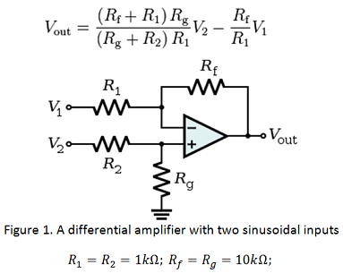
Procedure -
1. Design the circuit as seen in Figure 1 by following the same procedure as in previous lab session.
2. Use Vac for input sources. Make the amplitude of V1 input source equal to 1V and V2 to 2V. This is required for doing the AC sweep.
3. Open a new simulation profile and run "AC Sweep" analysis with the following parameters: (Simulation settings -> AC sweep -> logarithmic -> from 10Hz to 1MegHz, point/decade =1000)
4. Insert single voltage probe at the output terminal. Run the simulation and capture the frequency response and phase shift plots using the procedure mentioned in the "RC filter" experiment.
5. Simulate the input and output sinusoidal waveforms using "Time Domain" analysis and comment on the output amplitude and phase of the output with respect to the inputs. Change the input to 100Hz Vsin sine wave for both V1 and V2 but keep the amplitudes same. Does it correspond to the theoretical value?
2. Summing Amplifier - The summing amplifier, sums the different inputs and then amplifies them. Therefore, the output voltage is given by:
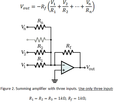
6. Repeat steps 1 - 5 of the above procedure for the summing amplifier with three inputs using V3 = 3V.
7. Remove one of the resistors and inputs (V3), hence summing only V1 and V2. Let V1 = 100 Hz and V2 = 10kHz. Use time domain analysis to show the input and output waveforms and comment on the same.
(Simulation settings: Run to time = 50ms; Step size = 0.1us)
8. In addition, instead of sinusoidal waveform, apply Vdc of the same voltages and comment on the output.
(Simulation settings: same as step 7 above).