Reference no: EM132490093
ENEE20002 - Advanced Electrical Machines and Drives Assignment Help, School of Engineering & Technology - Central Queensland University, Australia
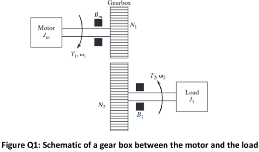
Question 1 - Schematic of a gear box between the motor and the load is shown in Figure Q1. N1 and N2 are the number of teeth in each gear wheel. The viscous damping constant and inertia of the motor shaft and load shaft are Bm, Jm and B1, J1 respectively. The torque and speed of the motor shaft and load shaft are T1, ω1 and T2, ω2 respectively.
a. Derive the equation relating T1, ω1 and T2, ω2.
b. Derive the equation relating N1, ω1 and N2, ω2.
c. Derive the expression for total equivalent inertia of the system referred to motor shaft J.
d. Derive the expression for total equivalent viscous damping constant of the system referred to motor shaft B.
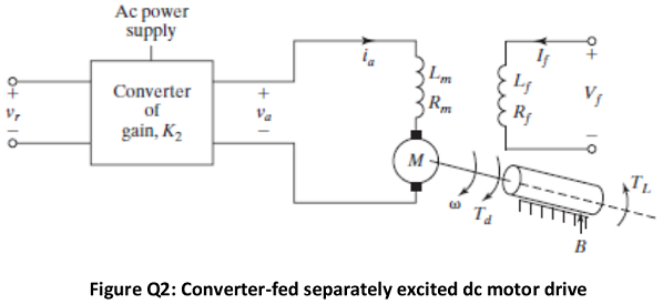
Question 2 - The circuit arrangement of a converter- fed separately excited dc motor drive with open- loop control is shown in Figure Q2. The motor speed is adjusted by setting reference (or control) voltage vr. Assuming a linear power converter of gain K2, and if the motor field current If and the back emf constant Kv remain constant during any transient disturbances;
a. Derive the time domain dynamical system equations for the DC motor.
b. Assuming zero initial conditions, obtain the Laplace transforms of your equations in (a).
c. Hence, derive the open-loop block diagram of the separately excited dc motor drive.
Question 3 - A dc motor has the following per - unit parameters in usual notations: L = 0.2, R = 0.1, ψ = 1, J = 200, and b = 0.1.
a. Design a closed loop PI current controller using internal model control (the same as pole zero cancellation) to achieve 10 times faster current dynamics compared to open loop current dynamics.
b. Use a SIMULINK model to verify the performance of the current loop (you are required to submit the SIMULINK model with your submission). Include the graphs of open loop and closed loop step responses of the armature current in the submission.
c. Design a outer PI controller using Internal Model Control approach to control the speed of the DC motor (keep the closed loop speed controller bandwidth to be 0.1 times the current controller bandwidth) - assume a power amplifier gain of 1 pu.
d. Develop a SIMULINK model for the complete DC drive system and present simulated waveforms to prove that your closed loop current controller as well as the closed loop speed controller performs according to the design specifications (you are required to submit the SIMULINK model with your submission). Include the graphs of open loop and closed loop step responses of the speed in the submission.
Question 4 - Calculate the sequence components of the following line - to - neutral voltages with abc sequence:
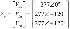
Is this a balanced system? Justify your answer.
Question 5 - Block diagram for the αβ (i.e. dq to αβ) transformation is given below.
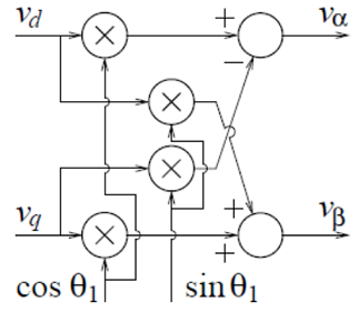
a. Observe the signal flaw in the block diagram and write the equations for vα and vβ in terms of vd, vq and ?1.
b. Now write the equations for vd and vq in terms of vα, vβ and ?1.
c. Draw the block diagram representing your equations in (b). In other words, this is representing αβ to dq transformation in block diagram form.