Reference no: EM132398929 , Length: word count : 1000
ELEC376 –Electronic Devices and Systems, Macquarie University, Australia
Module-3 Laboratory worksheet
INTRODUCTION
Lab module-3 is designed to build on your understanding of mixers. It concerns with the simulation, implementation and analysis of frequency doubler and a mixer. This lab module will run for 2 weeks (in two parts). For simulations, you will use a SPICE simulation tool called LTspice. The circuits will be implemented on a breadboard using BJTs available in the lab. As you are now more familiar with the concepts and implementation, there are lesser number of steps and instructions, that means more freedom to you on how to approach the lab problem.
PART-1 MIXER SIMULATION
PRE-LAB1
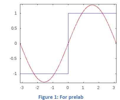
A1. Write down the expanded equation for the square wave (in blue) shown in Figure-1 up to 5 terms.
A2. If the square wave in the above equation was passed through a rectifying diode (assume an ideal diode with no nonlinearity) what is the new expanded equation for the rectified square wave?
WORK MODULE1
(a1) Wire up the circuit given in Error! Reference source not found. in LTspice. This is a mixer circuit. Give the local oscillator signal (LO) of 5KHz pulses with 50% duty cycle and the RF signal of 7KHz sine wave.

Simple mixer
(b1) The output is taken at the collector of Q1. Observe the output signal in the time domain and find out the various frequency components in the output using FFT.
(c1) Focus on the first five frequency components in FFT and explain where each of them may originate from.
Advanced mixer
(d1) Implement the circuit shown in figure3. Give LO =50KHz, 1V peak and RF=5KHz 1V peak.

(e1) Identify the current source, differential pair and buffer in the circuit.
(f1) Check for the mixed signals of the first order.
(g1) Imagine you have an input signal of 5KHz as before and you need to double that frequency, modify the circuit so that you have a frequency doubler.
PART-2 MIXER IMPLEMENATION
PRE-LAB2
List the advantages and disadvantages of an unbalanced, single balanced and a double balanced mixer.
What kind of balanced circuit is the mixer in figure-2?
WORK MODULE2
Simple mixer implementation
(a2) Implement the circuit shown in Figure-2 on a breadboard using BJT transistors.
(b2) Connect the LO and RF signals using a frequency generator and verify the outputs using an oscilloscope and a frequency analyser.
(c2) Comment on the leakage of signals.
(d2) Check the frequency doubling capacity of your circuit.
e2) Increase the frequency to a very high frequency and comment on the leakage of the LO at the output. Tip: Use the spectrum
analyser to check the relative strengths of frequencies.
(f2) Going back to the question in (a2), implement an RC circuit at the output to extract the LO-RF frequency (the difference frequency). Comment on its performance.