Reference no: EM132546396
ELEC 10003 DC Electrical Circuit Analysis - Middle East College
Learning Outcome 1: Apply mesh, superposition and source transformation for dc electrical circuits; and
Learning Outcome 2: Compare and contrast the different circuit analysis techniques.
Assignment Objective
o To study and apply various analysis techniques to solve DC electriconic circuits
Question 1: Using Mesh analysis, find the voltage a cross R5 for the circuit in Figure 1.
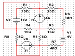
Figure 1
Question 2: a. For the network in given in figure 2, find out the equivalent resistance seen at the terminals A-B f using Δ to Y / Y to Δconversion.
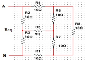
Figure 2
b. Mention any two pre requisite for applying superposition theorem for the solution of a network. ( explain each point in details)
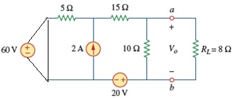
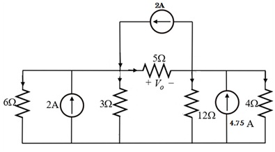
Question 3: Determine the Thevenin equivalent circuits at the terminal a b to find V0 for the network shown in figure 3.
Question 4:
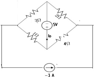
a. For the circuit shown below in figure 4, find the current Io using superposition theorem.
b. Consider the circuit shown in Figure 5. Find the value of the V0 by using source transformations.
Electronic Circuits
Learning Outcome 1. Implement small signal amplifier circuits using compound configurations of transistorsand report qualitative and quantitative data;
Learning Outcome 2. Interpret and outline electronic circuits using semiconductor devices considering the environmental implications of the design; and
Learning Outcome 3. Understand the values of using and sharing resources and knowledge for mutual enrichment while working in groups.
Question 1:
for the transistor circuit in figure1 with VCE = 7.2V ,IE =4 mA and IB= 20 uA,
a. Sketch re equivalent model circuit,
b. Determine the following;
i. re
ii. input impedance
iii. output impedance
iv. voltage gain(Av)
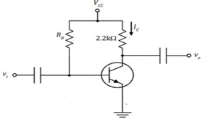
Figure 1
Question 2:
A cascade amplifier is a twoport network designed with amplifiers which are connected in series when every amplifier transmits its o/p to the second amplifiers input. for the BJT cascade amplifier of figure 2, calculate VB ,Vc ,VE,IE.
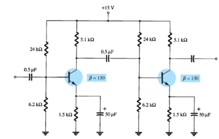
Figure 2
Question 3:
a. Sketch Common-emitter re equivalent model. If IE(dc) =1.2 mA ,β= 120 , and ro = 40k .
b. Find the value of source resistor and drain resistor for the circuit shown below in figure 3 and then draw self bias JFET including effect of Rs and r0=∞.
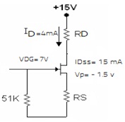
Figure 3
Question 4:
a. listand explain in detail any three advantages of a Darlington pair compared to common collector amplifier?
b. Illustrate if the given statement is correct or not by comparingcommon base circuit in approximate- hybrid and re - model, hfb= -1.
Attachment:- DC Electrical Circuit Analysis.rar