Reference no: EM133135801
EG55P7 Process plant equipment and operations - University of Aberdeen
Problem 1
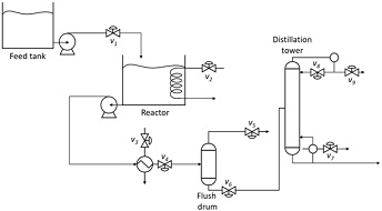
You are responsible for the section of the chemical plant shown in Figure 1. In this section, a feed stream is delivered from a storage tank to a reactor vessel, where an endothermic reaction takes place. The reactor products are further separated into volatile and non-volatile components using a flush drum. The liquid products of the flush drum are finally fractionated in a distillation column.

Figure 1: Plant consisting of feed tank, reactor, flush separation, and distillation column.
For all answers to the question below, you can use only the control valves present in Figure 1, but you are free to select sensors, feedback controllers and any calculation blocks, as needed.
1. You are initially tasked with developing a basic process control strategy that ensures the safety and operability of this plant and maintains important process variables close to normal operating values.
Provide an updated schematic that shows all control loops you propose to use. Justify the reasoning for the need to include each controller, briefly explaining how it contributes to the plant's safety and operability.
2. During operation of the plant section, it has been observed that the pressure of the steam pipelines used as heating medium experiences oscillations that cause unacceptable deviations from setpoints of the controlled variables.
Update the basic process control scheme from part 1 to account for the latter issue. The proposed design should achieve its objective while ensuring the smooth operation of the plant and the possibility of operator errors.
3. Strong market demand suggests operating the plant at maximum production level. There are however three possible factors that could limit the operation of this plant and need to be considered during plant throughput maximization: a)Heating medium availability for the reactor
b) Maximum flow of vapor product from the flash drum
c) Maximum reboiler duty possible in the distillation tower.
You are tasked with enhancing the control strategy of the plant from part 2 by designing a control system that achieves as primary objective the highest production rate in steady state. Secondary objectives of the design are its smooth and fast dynamic response that accounts for possible errors of operators.
Analyse how your proposed control design monitors and ensures that the three limitations above are not violated. Further discuss how the control scheme accounts for these limitations simultaneously while aiming at maximizing production and provide an updated schematic of your proposed control design. Clearly explain the reasoning behind all design decisions taken, including setpoints chosen, to demonstrate the functioning of the scheme.
Problem 2
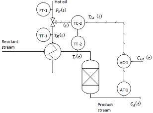
Consider the packed-bed reactor process shown in Figure 2. The inlet stream is pre-heated before entering the reactor in a heat exchanger that operates with hot oil. The control objective is to tightly regulate the exit concentration of the reactor CA(t) via the composition controller AC-1, while the most significant disturbance has been identified to be the heating medium temperature TH(t) measured by sensor TT-1. Due to this, the control engineer has proposed the cascade control scheme shown in Figure 2. The temperature of the reactant stream exiting the heat exchanger Tl(t), as measured by sensor TT-2, is used as a secondary control variable. AC-1 generates a temperature setpoint for the secondary controller TC-2 that uses TT-2 readings as its measurement. In turn, this secondary controller regulates the flowrate of the hot oil FH(t).
The relevant transfer functions and the units of their gains are the following, with all time constants appearing below in units of minutes:
• Reactor concentration in relation to its inlet temperature: C ____ TAl((ss)) = 40s.+81 [kmol?⁄m3]
• Reactor inlet temperature in relation to hot oil flowrate: F THl((s)) = (3s+11)(s+1) [m?3⁄h]
• Reactor inlet temperature in relation to hot oil temperature: TTHl((s)) = 2s1+1 [ ]
• Control valve: FMH((s)) = 0.23s+1 [m%CO3⁄h]
• Composition analyser/transmitter (AT-1): C CA,m(s(s)) = 0.5 [kmol %TO⁄m3]
A
• Temperature transmitter (TT-2): T Tl,m(s(s)) = 0.5 [%TO °c ]
(a) Draw the block diagram of this system including all transfer functions, showing clearly the variables and units of all connections.
(b) Apply the Routh-Hurwitz stability criterion to find the ultimate gain Kcu and ultimate period of oscillation Tu of the secondary control loop, assuming a proportional controller. Tune this proportional controller at a gain value equal to half of Kcu.
(c) Using the kc value obtained from (b), apply the Routh-Hurwitz stability criterion to find the ultimate gain kcu and ultimate period of oscillation ωc of the primary control loop, assuming again a proportional controller.
(d) For the cascade system in Figure 2, describe qualitatively how well it responds to the following disturbances for which it was not specifically designed: Reactant feed stream temperature, Reactant feed stream flowrate, Reactant feed stream composition and Heating oil pressure. For the analysis, specifically consider the effect of these disturbances on the process and its control objective.

Figure 2. Closed loop system for Problem 2
Attachment:- Process plant equipment and operations.rar