Reference no: EM132539721
EEET 4057 Power System Fundamentals - University of South Australia
numerical answers:
• Give answers to three or four significant figures, e.g. 2.123MVAr, unless the answer is an exact number
e.g. 2.000, in which case 2 is acceptable. Note that a ½ mark penalty applies to too few significant figures.
• Give answers with SI units, unless otherwise specified in the question.
o Note that marks are not awarded for units, however a ½ mark penalty applies for incorrect units.
• The first mistake is penalised at 1 mark if the question is worth 2 marks or more.
Question 1) Refer to the five bus system shown below, where all values are given in pu on a 300MVA base. Buses 2, 4 and 5 are load buses. Impedances of all lines and the tap-changing transformer are shown in pu values in Figure 1. Note that the tap-changer is connected to bus 5. Fort parts a) and b) set the tap changer to a position of 0.9999 pu.
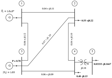
a) Use MATLAB functions lfgauss and lfnewton to find power flow solution for the system, accurate to 0.0000001pu.
i) Provide your busdata and linedata matrices, as well as a screenshot of the Command Window printout for the Gauss-Seidel method.
ii) Answer the following questions:
(1) Explain which method is faster by comparing the number of iterations of each method.
(2) Explain if any of the bus voltages need to be corrected, and what can be done about this?
b) Draw the power flow diagram showing voltages and powers for all busses and power losses in all lines. Show bus voltages (in pu) using green. Show real power (in MW) using blue and reactive power (in MVAr) using red.
c) Using the Newton-Raphson method, adjust the tap changer position between 0.90 and 1.10 in increments of 0.01, until you find a case where the voltage at bus 5 is as close as possible to 1 pu.
i) Record the tap changer position and the resulting magnitude of voltage at bus 5, in pu.
ii) Paste the screenshot of the Command Window showing the bus voltages.
d) Move the tap-changer such that it is located on bus 4.
i) Adjust the tap changer position between 0.90 and 1.10 in increments of 0.01, until you find a case where the voltage at bus 5 is as close as possible to 1 pu. Record the tap changer position and the magnitude of bus 5 voltage in pu.
ii) Paste the updated linedata matrix.
Question 2) Consider the single-line diagram of a five-bus power system in the Figure 2. Each generator is represented by an emf behind the transient reactance. All impedances are expressed in pu on a common MVA base. All resistances and shunt capacitances are neglected. The generators are operating at no load at the rated voltage with their emfs in phase. A bolted fault occurs at bus 5.
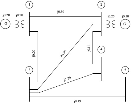
a) Using Thevenin's theorem, obtain the impedance to the point of fault and the fault current in pu.
b) Determine the bus voltages and line currents during the fault.
c) Repeat part a) if the fault now occurs at bus 3, through fault impedance, Zf = j 0.19 pu. Assumed that the fault at bus 5 has been cleared (resolved).
Question 3: A 3-phase unbalanced source with the following phase-to-neutral voltages is applied to the circuit shown below. The load series impedance per phase is Zs = 10 + j 40 and the mutual impedance between phases is Zm = j 5. The load source neutrals are solidly grounded.
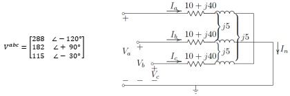
Use MATLAB to determine all of the following (include cropped screenshots for each part, and copy [click ‘Edit' then ‘Copy Figure' on Figure window' / paste the figures generated by the MATLAB scripts). Hint: use Q10.7 as a guide from the ‘unbalanced faults' tutorial.
a) The load sequence impedance matrix, Z012 = A-1ZabcA.
b) The symmetrical components of voltage (rectangular and polar forms). Paste the MATLAB figure.
c) The symmetrical components of the current (rectangular and polar forms).
d) The load phase currents (rectangular and polar forms). Paste the MATLAB figure.
e) The complex power delivered to the load in terms of symmetrical components, i.e.:
S3$ = V0I0× + V1I1× + V2I2×
f) The complex power delivered to the load by summing the power in each phase, i.e.:
S3$ = V I× + V I× + V I×
a a b b c c
g) Compare the results of parts e) and f).
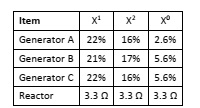
Question 4) Three 33 MVA, 33 kV synchronous generators, A, B, and C, are connected via three reactors to a common bus bar, as shown in Figure 4. The neutrals of generators B and C are solidly grounded, whilst the neutral of generator A is grounded through a separate reactor of 1.65 Ω. The generator data and the reactance of the reactors is summarised in Table 4. Neglect pre-fault currents and assume the generators are operating at their rated voltage.
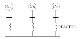
a) Calculate and draw the zero, positive and negative sequence networks.
b) Determine the fault current in phase a, for a single line-to-ground fault occurring on phase a of the common bus bar.
c) Determine the fault current for a bolted double line fault occurring between phases b and c.
d) Determine the fault current for a bolted a double line-to-ground fault occurring on phases b and c.
Question 5) Use Power Factory to complete Practical 4 for this course and follow the instructions listed in that handout.
Attachment:- Power System Fundamentals.rar