Reference no: EM132842227
EAS109 Thermo-Fluid Mechanics - Singapore University of Social Sciences
Question 1
(a) A pool of volume X (in m3) is to be filled with water using a hose of diameter D (in m). If the average discharge velocity u (in m/s) and the filling time is t (in s), obtain a relationship for the volume of the pool based on the considerations of the quantities involved.
(b) Interpret the equation you develop for dimensional consistency.
(c) Apply if any, the constants of proportionality and advise on how they might be obtained.
Question 2
Consider the flow of air through a wind turbine whose blades sweep an area of D (in m). The average air velocity through the swept area is V (in m/s) and the density of the local air is ρ (in kg/m3).
On the bases of the units of the quantities involved, identify that the mass flow rate of air (in kg/s) through the swept area is proportional to the air density, the wind velocity and the square of the diameter of the swept area.
Question 3
With the aid of a neat sketch, derive an expression to describe how a Pitot plus Static Tube combination be used to calculate flow velocity in a pipe delivering fluid flow. Explain your assumptions before you proceed with your derivation.
A Pitot plus Static Tube is used to measure the velocity if an aircraft flying at 3km. If the differential pressure between the Stagnation Pressure and static pressure is 3 kPa, recognise the velocity of the aircraft in m/s and km/h.
[The density of the atmosphere, ρ at an elevation of 3km is 0.909 kgm-3]
Question 4
A 1kW iron for ironing clothes whose base plate is made of 0.5cm thick aluminium alloy 2024- T6 (ρ = 2770 kg/m3 and cp = 875 kJ/kg0C). The base plate has a surface area of 0.03m2.
Initially, the iron is in equilibrium with the ambient air at 220C.
Assuming, 90% of the heat generated in the resistance wires is transferred to the plate, identify the minimum time needed for the plate temperature to reach 2000C.
Question 5
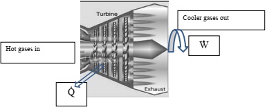
Hot gases in a turbine enters at a flow rate of 10kg/s, and the power produced by the turbine is 10MW. The specific enthalpy at the inlet and outlet are 1500 kJ/kg and 300 kJ/kg respectively. The inlet velocity is 50 m/s and outlet velocity is 120 m/s. Apply the data to evaluate the rate of heat rejection from the turbine. Assume negligible potential energy changes.
[Note W· is work done per second, which is power. Q· is heat transfer per second.]

Question 6
When tested in a test cell, a jet engine takes in a mass flow of 25kg/s of air and 0.25kg/s of fuel. The air velocity at inlet is 150 m/s and at exhaust is 500 m/s.
(a) Draw a sketch for the flows into and out of the jet engine. Clearly indicate a suitable control volume that you will use to help you solve the problem using momentum analysis of this flow situation.
(b) Explain that the thrust developed by the engine exceeds 8kN. Identify TWO (2) assumptions you make in your analysis of this jet engine.
Question 7
Air at 250C flows through a diffuser. At the inlet, 1, the velocity and area are 100 m/ and 0.5m2. At the exit, 2 the area is 1.5 m/s.
(a) Realise a sketch of this set-up. Identify all flow parameters mentioned. Using the Perfect Gas Law in Thermodynamics, evaluate the density, ρ, of the air at inlet conditions. Analyse and explain why compressibility effects may neglected in these circumstances. Apply the Continuity Equation in Fluid Mechanics, to identify the exit velocity.
[The specific gas constant for air R = 287 J/kgK
(b) Finally, invoking the Principle of Conservation of Energy through the Bernoulli equation, interpret the diffuser pressure rise, clearly explaining all your starting assumptions.
Question 8
A pipe of 10cm diameter is connected to a nozzle. A flanged, bolted connection is used to secure the nozzle onto the pipe. Water discharges through the nozzle jet of diameter 3cm at a flow rate of 25 litres/s to the atmosphere. Assume that frictional effects are negligible.
[Take the density of water to be 1000 kg/m3]
(a) Draw a neat sketch of the setup. Label the pipe, nozzle and flange.
Also, draw and identify the control-volume which you will use for your analysis and calculation.
(b) Explain that the (gauge) pressure in the pipe, just before the nozzle, is 620 kPa.
(c) Using the control-volume you drew in (a), describe the force required by the flanged bolts to hold the nozzle to the hose.
Question 9
An aircraft has a wing area of 30 m2, a lift coefficient of 0.45 at take-off settings, and a total mass of 2.8 tonnes.
(a) Apply the data to identify the take-off speed of this aircraft at sea level under standard atmospheric conditions (air density at sea-level, ρair = 1.225 kg/m3) and that that the lift and drag are produced solely by the mainplane.
Describe the numerical value of the wing loading?
(b) The aircraft after take-off cruises at 300 km/h with a cruising drag coefficient of 0.035. Recognise the power required to maintain the required cruise speed.
Question 10
Summarize what you have learnt from this course EAS109 in two A4 size papers. The contents will contain key knowledge points in Study Units 1 to 6.
Attachment:- Thermo-Fluid Mechanics.rar