Reference no: EM132295559
LAB Assignment -
Configuring Interfaces for RIP
The routers need to be able to exchange routing information with other interfaces and routers. RIP (Routing Information Protocol) will be used in this part.
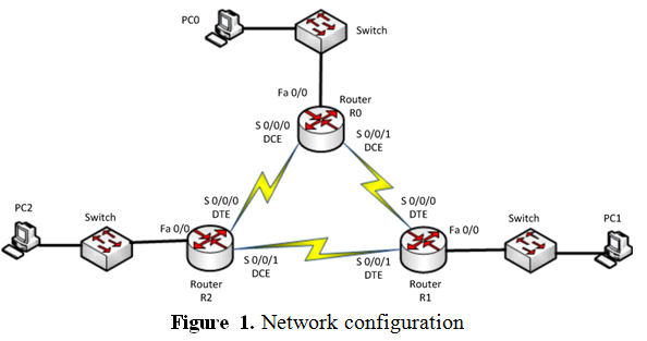
Use the table below to configure the respective interfaces on each router.
|
Device
|
Interface
|
IP address
|
Subnet Mask
|
|
Router 0
|
Fastether 0/0
|
192.168.50.1
|
255.255.255.0
|
|
Serial 0/0/0
|
192.168.10.7
|
255.255.255.0
|
|
Serial 0/0/1
|
192.168.30.1
|
255.255.255.0
|
|
Router 1
|
Fastether 0/0
|
192.168.60.1
|
255.255.255.0
|
|
Serial 0/0/0
|
192.168.30.2
|
255.255.255.0
|
|
Serial 0/0/1
|
192.168.20.2
|
255.255.255.0
|
|
Router 2
|
Fastether 0/0
|
192.168.70.1
|
255.255.255.0
|
|
Serial 0/0/0
|
192.168.10.6
|
255.255.255.0
|
|
Serial 0/0/1
|
192.168.20.1
|
255.255.255.0
|
At each PC, configure IP addresses and Gateway addresses as shown below.
PC0 - 192.168.50.2 255.255.255.0 Gateway: 192.168. 50.1
PC1 - 192.168.60.2 255.255.255.0 Gateway: 192.168. 60.1
PC2 - 192.168.70.2 255.255.255.0 Gateway: 192.168. 70.1
Use below commands to configure the router.
At router 1, for fastether interface
Router1(config)#interface fastether 0/0
Router1(config-if)#ip address 192.168.60.1 255.255.255.0
Router1(config-if)#no shutdown
Router1(config-if)#exit
For serial interface
Router1(config)#interface s 0/0/0
Router1(config-if)#ip address 192.168.30.2 255.255.255.0
Router1(config-if)#no shutdown
Router1(config-if)#exit
Configure the interfaces for all three routers.
Note: For Router 0, configure the following clock rates as well.
Router0(config)#interface s 0/0/0
Router0(config-if)#clock rate 2000000
Router0(config-if)#exit
Router0(config)#interface s 0/0/1
Router0(config-if)#clock rate 2000000
Router0(config-if)#exit
Now configure the router with RIP.
In RIP, each router advertises its neighbor networks to all other routers. For example, at router 2, it should advertise its neighbor networks such as 192.168.10.0, 192.168.70.0, and 192.168.20.0 networks. Following commands will advertise the networks at router 2.
Router2(config)# router rip
Router2(config-router)# network 192.168.10.0
Router2(config-router)# network 192.168.20.0
Router2(config-router)# network 192.168.70.0
1. Configure Router 0 and 1 for RIP. Show the routing tables of all routers. You may need to wait for converging time.
2. Verifying the connectivity by showing ping results at PC1 to PC0 and PC2.
3. Disconnect link between router 1 and router 2. Wait for some time and ping from PC1 to PC0 and PC2. Once they are successful, look at routing table at R2 and compare it with before the link failure. Explain how they are different. Show updated routing table.
To remove the RIP at router, use the command "Router2(config)# no router rip".
Configuring Interfaces for OSPF -
In this section, we will try to gain an understanding of advanced hierarchical routing configurations used by OSPF. We will configure and verify the operation of single-area topology.
OSPF Areas - An area is defined as a collection of end systems, routers and transmission facilities. Each area is defined by a unique number and this number is configured into each router.
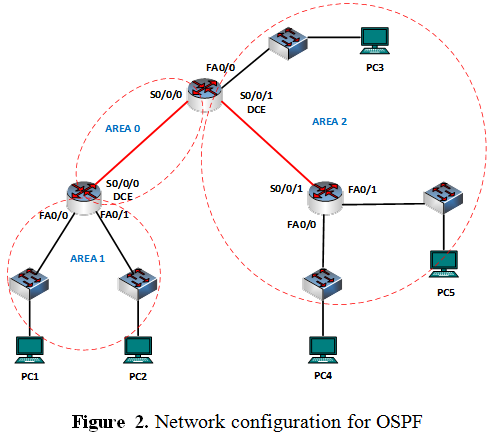
Create the network shown in figure 2. Note that DCE end is on s0/0/0 at Router 1 and s0/0/1 at Router 2. Use the table below to configure the respective interfaces on each router
|
Device
|
Interface
|
IP address
|
Subnet Mask
|
|
Router 1
|
Serial 0/0/0 (DCE)
|
192.168.1.1
|
255.255.255.0
|
|
Fastether 0/0
|
192.168.10.1
|
255.255.255.0
|
|
Fastether 0/1
|
192.168.20.1
|
255.255.255.0
|
|
Router 2
|
Serial 0/0/0
|
192.168.1.2
|
255.255.255.0
|
|
Serial 0/0/1 (DCE)
|
192.168.2.1
|
255.255.255.0
|
|
Fastether 0/0
|
192.168.30.1
|
255.255.255.0
|
|
Router 3
|
Serial 0/0/1
|
192.168.2.2
|
255.255.255.0
|
|
Fastether 0/0
|
192.168.40.1
|
255.255.255.0
|
|
Fastether 0/1
|
192.168.50.1
|
255.255.255.0
|
For each PC, configure them as below
PC1 - 192.168.10.5 255.255.255.0 Gateway: 192.168. 10.1
PC2 - 192.168.20.5 255.255.255.0 Gateway: 192.168. 20.1
PC3 - 192.168.30.5 255.255.255.0 Gateway: 192.168. 30.1
PC4 - 192.168.40.5 255.255.255.0 Gateway: 192.168. 40.1
PC5 - 192.168.50.5 255.255.255.0 Gateway: 192.168. 50.1
To define the interfaces on which OSPF runs and to define the area ID for those interfaces, use the network area router configuration command. To disable OSPF routing for interfaces defined with the address wildcard-mask pair, use the no form of this command.
network address wildcard-mask area area-id
no network address wildcard-mask area area-id
There are 3 areas in this network and now configure OSPF routing protocol at each router using following commands. We will use ospf process ID of 1.
At Router 1
Router0(config)# router ospf 1
Router0(config-router)# network 192.168.1.0 0.0.0.255 area 0
Router0(config-router)# network 192.168.10.0 0.0.0.255 area 1
Router0(config-router)# network 192.168.20.0 0.0.0.255 area 1
Now configure router 2 and 3.
4. Configure router 2 and 3 for OSPF using above commands. You may need to wait for converging time. Now check the connectivity of the network. You should be able to ping all other devices at any PC. Check the connectivity by pinging PC2, 3, 4, and 5 from PC1. Show your successful ping results.
5. Use "show ip ospf interface" command to display a summary of interface at each router. Find the following information for all interfaces at each router. IP address, area, process ID, router ID, network type, and cost.
6. Use "show ip protocols" command to verify OSPF setting on each router. Find router ID, number of areas in the router, maximum path, and routing for networks.
Download the packet tracer file on the blackboard and answer following questions.
7. Draw the network topology. Show only routers.
8. Configure RIP on each router. Use the routing tables from all routers to find the path the rest of network at each router.
9. Now configure OSPF each router using following information. Then, use the routing tables from all routers to find the path the rest of network at each router.
Area 0: Router 2 (S0/2/0 and Fa0/1), Router 3 (S0/2/0 and S0/3/0), Router 4 (S0/2/0 and Fa0/0).
Area 1: Router 3 (S0/2/1), Router 4 (Fa0/1), Router 5 (S0/2/0, Fa0/0, and Fa0/1).
Area 2: Router 0, Router 1, Router 2 (Fa0/0 and S0/2/1), Router 3 (Fa0/0).
Note - Need only questions 7, 8, 9.