Reference no: EM132251844
Q1. (a) Using DeMorgan's theorem determine the negative equivalent gate for the AND gate and the NOR gate. Illustrate your answers with diagrams and De Morgan's theorem.
Q2. Write down the Boolean expression which satisfies the following statementan construct the logic circuit it defines: "The output is true if A OR B is true, AND if A AND B are NOT true". Suggest a possible single gate that might perform the same operation carried out by this circuit.
Q3. (i) Using sum of products (SoP), i.e., sum of Minterms, write down the Boolean expression represented by the following truth table. (ii) Using a K-map simplify this expression and implement the digital circuit.
|
A
|
B
|
C
|
Y
|
|
0
|
0
|
0
|
0
|
|
0
|
0
|
1
|
1
|
|
0
|
1
|
0
|
0
|
|
0
|
1
|
1
|
0
|
|
1
|
0
|
0
|
0
|
|
1
|
0
|
1
|
1
|
|
1
|
1
|
0
|
1
|
|
1
|
1
|
1
|
0
|
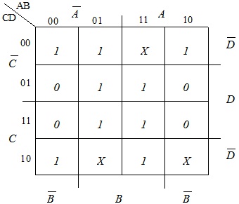
Q4. Using the K-map below, write down the logic function in the SoP term (i.e., in ∑ form). The X's in the K-map represent the "Don't care" condition.
Q5. (a) Explain the difference between active low and active high logic inputs. Draw a circuit diagram of an active low latch using appropriate gates, and draw its truth table.
(b) Using simple diagrams and with the help of XOR gates construct a 4-bit adder/subtractor circuit.
Q6. (a) Determine the negative value of the binary number 10110010 using the 2s complement method.
(b) Complete the following truth table for the two bit parallel adder.
|
A1
|
B1
|
A0
|
B0
|
CO0
|
CO1
|
S1
|
S0
|
|
0
|
0
|
0
|
0
|
|
|
|
|
|
0
|
0
|
0
|
1
|
|
|
|
|
|
0
|
0
|
1
|
0
|
|
|
|
|
|
0
|
0
|
1
|
1
|
|
|
|
|
|
0
|
1
|
0
|
0
|
|
|
|
|
|
0
|
1
|
0
|
1
|
|
|
|
|
|
0
|
1
|
1
|
0
|
|
|
|
|
|
0
|
1
|
1
|
1
|
|
|
|
|
|
1
|
0
|
0
|
0
|
|
|
|
|
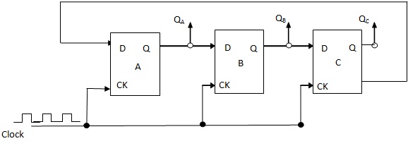
Q7. Analyse the following D-flip flop circuit and draw the truth table (assume initial states of QA = 0, QB = 0, and QC = 0).
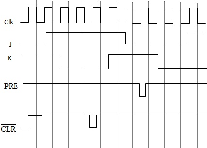
Q8. (i) Draw the full logic symbol of the J-K flip flop.
_______ ______
(ii) A falling-edge triggered J-K flip flop having the J, K, Clock, PRESET and CLEAR input waveforms applied as shown in the diagram given below. Determine the output waveform Q for these given inputs, and indicate on the diagram the designation (name) of each output state.
(iii) Draw the truth table of this J-K flip flop given in (ii).