Draw bending moment and shear force diagram

Assignment Help Mechanical Engineering
Reference no: EM131025651

Question 1:

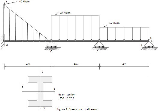
Q1 Figure 1 shows a steel beam used in one of the floors of a chemical plant. Using the method of superposition calculate the reactions at the each of the supports and the fixed end moments. Draw Bending Moment (BM) and shear force diagram for the beam AB. (Standard formulas of general loading cases are provided in the study desk)

Q2 Using the stiffness method, determine the reactions at the supports and the fixed end moment of the steel beam shown in Figure 1. Show the stiffness matrices for each member and the assembled global stiffness matrix. Use a convenient method for the solution such as inverse matrices or use of simultaneous equations. E (Steel) is 200 GPa and Beam section details can be found in the One Steel product catalogue. (An extract of one steel catalogue will be posted on the study desk)

Q3 Perform a structural analysis using Creo3.0 simulate for the Steel beam as shown in Figure 1. Tabulate manual calculations and FEA results. Compare your FEA results with the calculated values of Q2.1 and Q2.2. You need to show beam's BM & SF plots, the beam's stress/strain plots and a deflection plot.
1640_Draw Bending Moment.jpg

Question 2:

Q1. Write a short note (not more than half A4 page) on your understanding on St. Venant's Principal for your engineering design analysis.

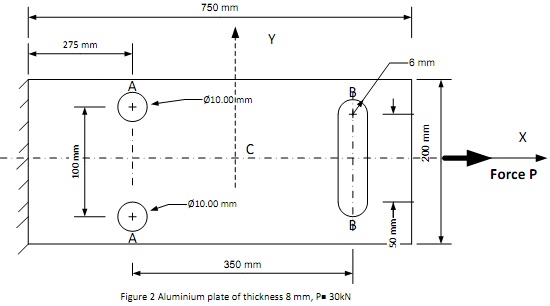
Q2. Perform an FE analysis on Creo 3.0 Simulate for the axially loaded 8 mm thick aluminium plate shown in Figure 2. You need to simplify the problem using the symmetry and create a coarse mesh first and then refine the mesh appropriately. A picture of the refined mesh and necessary details must be provided. Also you also need to show X-Y 2D plane plots and through thickness stress/strain plots whenever necessary.

(a) Plane Stress Case:

Estimate the "Stress Concentration Factor" Kt at stress raisers areas identified by letter A and B. Estimate the principal stress (Max) and strain (Max) and local stress/strain (X & Y) at C, the centre of the plate. Using the X & Y components of the strain , manually calculate X,Y stress components and Z strain component using generalized "Hooks Law". Show all necessary steps of manual calculations, (2D plane stress) X & Y stress/strain plots and Max principle stress/strain plots.

(b) Plane Strain Case:

Estimate the "Stress Concentration Factor" Kt at stress raisers areas identified by letter A and B. Estimate the principal stress (Max) and strain (Max) and local stress/strain (X & Y) at C, the centre of the plate. Using the X & Y components of the strain , manually calculate X,Y and Z stress components using generalized "Hooks Law". Show all necessary all necessary steps of manual calculations, (2D plane strain) X & Y stress/strain plots and Max principle stress/strain plots.

Q3. Perform a 3D analysis on Creo 3.0 Simulate for the axially loaded 8 mm thick aluminium plate shown in Figure 2:

(c) Estimate the "Stress Concentration Factor" Kt at stress raisers areas identified by letter A and B. Estimate the principal stress (Max) and strain (Max) and local stress/strain (X,Y & Z) at C, the centre of the plate. Tabulate Kt for cases a to c and comment on appropriate analysis for the axially loaded 8 mm thick aluminium plate. Show all necessary (3D analysis) X, Y & Z stress/strain plots and Max principle stress/strain plots.
1584_Draw Bending Moment1.jpg

Question 3:

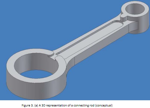
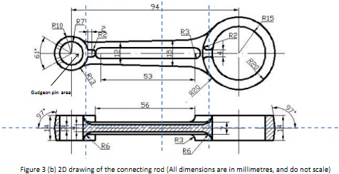
Figure 3 shows a conceptual model of a connecting rod which was prepared for an initial stress/strain analysis. The maximum normal operational pressure acting on the Gudgeon pin at the power stroke was estimated as 20MPa. The material of the connecting rod is steel alloy 42CrMo4 (E=198 GPa, Poisson ratio =0.3, Ult. Strength 800 MPa - 1000 MPa, Coef. of Expansion=17.3 x 10E-6 /0C)

(a) Create a suitable model to analyse the structural performances of the connecting rod at the maximum load application. You need to show, force applications, constraints and the refined model with the mesh using appropriate graphical representations.

(b) Perform a 3D Static analysis and show surface stress/strain plots and the stress/strain plots through the sections planes indicated by dotted lines.

You need to create a coarse mesh first and a then refine the mesh appropriately. A picture of the refined mesh and necessary details must be provided. Also you also need to show X-Y 2D plane plots and through thickness stress/strain plots whenever necessary. You are required to use symmetry for FEA modelling, as appropriate.
1328_Draw Bending Moment2.jpg

32_Draw Bending Moment3.jpg

Question 4:

Clearly explain by point form the procedure to calculate the reactions at the supports , the fixed end moment and the mid- span deflections of beam segments AC, CD and DB of steel beam shown in Figure 1 of Q1, using the stiffness method. You need to show sketches wherever necessary.

Reference no: EM131025651

Questions Cloud

Which of the following will shift the aggregate supply curve : Which of the following will shift the aggregate supply curve upward? Which of the following would shift the aggregate demand curve to the right
What is your decision about the hypothesis : You perform a hypothesis test at the .05 level of significance. Your computed p-value turns out to .042. What is your decision about the hypothesis.
Using the most recent income statement for two corporations : Find one large corporation included in the S&P 500. Then, find one of its largest competitors. Go to the investor relations portion of each corporation's homepage and find their most recent annual report. Using the most recent income statement (annua..
You need to raise in order to build your shipping terminal : Suppose your firm needs to raise $10.5 million to construct a new shipping terminal. As CFO, you plan to raise funds in the following manner: 60% of the funds will be raised by selling long term debt (bonds). 40% of the funds will be raised by retain..
Draw bending moment and shear force diagram : Draw Bending Moment (BM) and shear force diagram for the beam AB - Perform a structural analysis using Creo3.0 simulate for the Steel beam
Withdraws all of the interest earned to date and transfers : Juan deposits $1000 in a savings account that pays 8% compounded annually. Exactly 2 years later he deposits $3000; 2 years later he deposits $4000; and 4 years later he withdraws all of the interest earned to date and transfers it to an account that..
Find distribution function for x length of time component : The life length Y of a component used in a complex electronic system is known to have an exponential density with a mean of 100 hours. The component is replaced at failure or at age 200 hours, whichever comes first. Find the distribution function ..
What are the dimensions of the rectangle : The length of the rectangle is 2/3 of the width. The total perimeter is 40cm. What are the dimensions of the rectangle?
What will be the change in dd on the balance sheet : What will be the change in DD on the balance sheet of Bank A? What is the total change in required reserves and excess reserves on the balance sheet of Bank A? Suppose Bank A lends out all their ER to George. What will be the amount of the loan

Reviews

Write a Review

Mechanical Engineering Questions & Answers

  Package design

Package Design Brief: Assume you are the packaging engineer for a large consumer products company. In this company, the Packaging Design Briefs are initiated by the marketing group and forwarded to the Package Engineering group.

  Mechanical engineering questions

Define dynamic viscosity, Determine the centroid, Pressure due to the height of liquid, Advantage of changing the liquid, Calculate the total moment about the hinge of the seal gate.

  Automatic control

DOF system and Find the differential equation describing the system

  Write a paper on boyle''s law

Write a paper on Boyle's law and describe Compression and Combustion stroke . Also explain Charles's law and illustrate SI engine and CI engine.

  Verify the law for parallelogram of forces

To Verify the law for parallelogram of forces, law for triangle of forces and law of polygon of forces. These laws are very useful to calculate unknown forces in very short time.

  Discharge pressure of the compressor

What is the discharge revised discharge pressure of the compressor.

  The Case for Global Accounting Standards

The role of IFRS in both developing and developed capital markets.

  Wind turbine

Wind turbines are becoming more and more common as a method of energy production, wind turbines by their very nature are dynamic and are subject to and create their own internal and external kinematics and kinetics.

  Advanced design methodologies

8 x product engineering and design review (week 2 – 12), ~3 pages per item which must contain a brief description of the product then delve into concepts such as materials selection, manufacturing methods, life cycle analysis, recyclability and overa..

  Design of absorption column and the cooler

Design of absorption column and the cooler. Process design of other units should be completed along with pipe sizes.

  Determine the maximum total bending moment

Determine maximum total bending moment (static plus dynamic) of the beam under steady-state conditions.

  Force of the water on the gate

Determine the magnitude of the horizontal and vertical components of the force of the water on the gate.

Free Assignment Quote

Assured A++ Grade

Get guaranteed satisfaction & time on delivery in every assignment order you paid with us! We ensure premium quality solution document along with free turntin report!

All rights reserved! Copyrights ©2019-2020 ExpertsMind IT Educational Pvt Ltd