Reference no: EM131183100
DIGITAL SYSTEMS
LAB: COUNTER DESIGN
Objective: Given a desired counting sequence, design and build the counter using flip-flops and gates. Derive the flip-flop input equations using a state table and K-maps
Preparation (Pre-lab)
o Do the complete paper design for the counter specified in Design I. Your paper design must include the following items:
o State transition table for the counter
o K-maps for each of the flip-flop input equations.
o Minimized sum of products (SoP) equation for each flip-flop input signal.
Description
In this lab, you will design a unique counter that implements the state diagram shown in the figure below. Each student will be given an individualized count sequence to implement. The count values X1 - X6 shown in the figure will be some sequence of the numbers 1 - 6, with each number used only once. This circuit will simulate rolling a die.
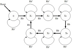
Figure 1. Counter State Diagram
Note that the counter has an input, Rb, which stands for "Roll button". The counter counts as long as Rb = 1, but when Rb = 0 the counter maintains the last count value.
There is one other possible state in a 3-bit counter design. For example if X1 to X6 correspond to state bits 001 to 110 and the reset state corresponds to state bits 000, the "missing" state has state bits 111. It is possible that the state machine could power-up in this state. If so, you must guarantee that the state machine does not remain stuck in this state, even when the reset switch is not pressed. Thus, the next state assignment from the missing state must be to one of the states in the count sequence, X1 to X6, or the reset state.
Design I. Moore Machine with the State Bits as the Outputs
Design the counter as a Moore machine where the state bits serve as the count outputs.
a) Draw a state transition table and derive the input equations for implementing the counter using D flip-flops and logic gates.
b) Enter your design in Quartus II. Use the 7474 or the DFF component for the D flip-flops, the 7447 component for the seven-segment display logic, INPUT and OUTPUT components and basic logic gates (AND, OR, NOT, etc.) Use an SW toggle switch for Rb and a KEY pushbutton switch for Reset. Display the output on HEX0 and turn off all the segments on HEX1-HEX7. This circuit should be clocked by the 27 MHz or 50 MHz clock signals available on the Altera DE2 board.
c) Verify your design by simulating in ModelSim. Print a copy of your simulation waveforms for one complete cycle for your lab report. Set the radix to Hex for the seven- segment output signal. Have your TA verify your simulation.
NOTE: In order to avoid timing violations in your gate-level simulation, you may need to make the first edge of the clock signal a fall edge rather than a rising edge as shown below.
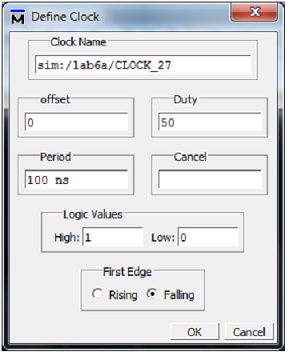
You should simulate with a clock period of 100 ns and run the simulation for 100 ns each step.
Design II. Mealy Machine
Design the counter as a Mealy machine. Do a complete paper design. However, you do not need to enter your design as a Quartus schematic or simulate your design. Compare the number of gates required for the Mealy machine with the number required for the Moore machine in Design I.
Implementation of Design I
Once your simulation for Design I works, download your design to the DE2 board and verify that your circuit works. Don't forget to import the pin assignments!! The output will change too fast to observe the sequence while the counter is counting, but you should observe that the counter stops on numbers 1 to 6 with about equal probability. If the die seems to be ‘unfair', check your simulation and your circuit carefully. Another debugging technique is to test your circuit with a slow clock so you can see the count sequence. (This circuit will be used as part of the final lab, so save your project files.) Have your TA verify your working circuit.
Lab Report
Each individual will be required to submit a lab report. Use the format specified in the "Lab Report Requirements" document available on the class web page. Be sure to include the following items in your lab report:
Q Lab cover sheet with TA verification for circuit simulation and performance
Q Graded pre-lab
Q Logic design documentation (truth table, K maps, logic equations) for both designs
Q Quartus II schematics for Design I
Q ModelSim simulation waveforms for Design I Answer the following questions in your Lab Report:
Q1: Compare Design I and Design II of the sequential circuit. Describe any advantages or disadvantages of the Moore design for this circuit.
Q2: A third design for the counter circuit might use a Moore machine where the state bits were not used as the outputs. For example, the state bits might be the binary count sequence 0 - 6.
How would this design would with Designs I and II (assuming your assigned count was not the straight binary count sequence 1 to 6)? Which design is likely to require the fewest gates? Justify your answer.
|
What is the future value at discount rate
: Cannonier, Inc., has identified an investment project with the following cash flows. Year Cash Flow 1 $ 1,090 2 1,320 3 1,540 4 2,280 If the discount rate is 7 percent, what is the future value of these cash flows in Year 4? What is the future value ..
|
|
How expensive and complex is the technology
: Describe and summarize your selected detection, inspection, or surveillance technology that could be used to increase law enforcement agency capabilities.
|
|
Calculate river city payroll departments cost per check
: Calculate River City payroll department's cost per check. Based on costs would it be cheaper to maintain the payroll department or contract out for the payroll services?
|
|
Rentable square foot project with average rents
: A company is considering of land that could be developed into a class A office project. At the present time, the company believes that the site could support a 300,000 rentable square foot project with average rents of $ 20 per square foot and operat..
|
|
Draw a state transition table and derive the input equations
: Design the counter as a Moore machine where the state bits serve as the count outputs. Draw a state transition table and derive the input equations for implementing the counter using D flip-flops and logic gates.
|
|
Evaluate the policy and regulatory implications of the case
: Include a literature review synthesising the existing literature relevant to the area of crime and regulation, provide a case analysis, explaining how and why the failure of regulation occurred, Analyse and evaluate the policy and regulatory implicat..
|
|
Do feel completely necessary to ensure national security
: Overall, do you feel that the controversial counterintelligence tactics used during COINTELPRO were necessary to protect U.S. national security? Are there any circumstances where you feel this type of domestic counterintelligence should be allowed?..
|
|
The investor uses straight line depreciation
: Assume that an investor acquired a property 5 years ago at a cost of $ 200000. The property was 15 years old at the time of purchase and was financed with a 75% mortgage at 11% interest for 25 years. The investor uses a straight line depreciation wit..
|
|
How many liters of each product are produced
: (a) How many Liters of C2H6 (g) are needed to react completely with 656.0 L of oxygen O2 (g), at STP to produce CO2 (g) and H2O (g)?
|