Reference no: EM13492
1. Draw a relay construction diagram and briefly explain the operation of a relay.
2. Define the terms normally open and normally closed.
3. Define the terms Set and Reset for relays.
4. Draw a latching circuit and interlocking circuit and briefly explain the operation of those two circuits.
5. Draw an electrical relay diagram rung showing a N/O contact of CR1(coil) in series witha N/C contact of CR2(Coil), operating a lamp L1.
6. A delay-on (TON) relay has a preset of 5.0 seconds. Explain how it reacts If if the coil terminals areenergized for
a) 8 seconds how long will its contacts be actuated.
b) 3 seconds
explain how it reacts
6.7. a. Explain the operation of basic motor STOP/START circuit shown below.
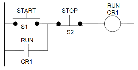
Figure: Relay Ladder Diagram for Basic STOP/START Circuit
7.8. b. The above figure below shows an OP OR gate combined with an AND gate to duplicate the logic of a ladder diagram that contains a start button, holding contacts, stop button and motor starter.
a) State the equivalents in the ladder diagram above(figure in Question 7), for A, B and C below
a) b) Compare the logic of the ladder diagram with the logic gate equivalent circuit and
b) c) Complete the truth table below.
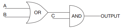
Figure: Combining an OP OR gate and an AND gate
Truth Table
A B C OUTPUT
0 0 0
0 0 1
0 1 0
0 1 1
1 0 0
1 0 1
1 1 0
1 1 1