Reference no: EM131452722
Computational Mechanics in Design Assignment
Question 1 -
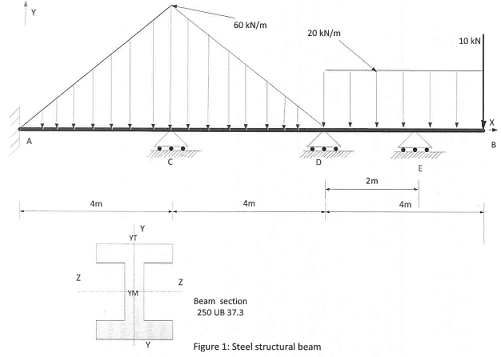
Q1. Using the stiffness method, determine the reactions at the supports and the fixed end moment of steel beam shown in Figure 1. Show the stiffness matrices for each member and the assembled global stiffness matrix. Use a convenient method for the solution such as inverse matrices or use of simultaneous equations. (E (Steel) is 200 GPa and Beam section details can be found in One Steel product catalogue. (An extract of one steel catalogue has been posted on the study desk). Manually calculate transverse shear stress distribution along the beam's section axis y-y from the top surface (yt) to centre of the beam section (yM) at the support E and the bending stresses of Top & Bottom surface of the beam section at the fixed end A..
Q2. Perform a FEA structural analysis using Creo3.0 simulate for the Steel beam as shown in Figure 1. Use 3D analysis (solid beam). Using FEA structural analysis results:
1. Draw a graph of a vertical displacement of the beam.
2. Draw a graph of a Bending stress plot for bottom and top surfaces of the beam. Show a fringe (contour) plot of bending stresses.
3. Draw a maximum shear stress plot along the beam axis.
4. Estimate the shear stress along the beam section at support E using FEA results. Draw a graph of estimated shear stress.
5. Tabulate manual calculations and FEA results for bending stress at fixed end A and transverse shear stress of the beam section at support E. Compare manual calculation and FEA results and briefly provide your judgement, if there is a significant discrepancies between manual and FEA results.
Question 2 -
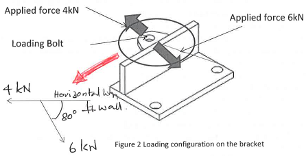
You need to watch Guest lecture posted on the study desk and adhered to the design & FEA criteria explained by the lecturer. The model and the drawing can be downloaded from the link provided in assignment area on the Study Desk. The bracket is to be bolted down to a steel plate of 80 mm width (from the right corner of the component). Two 4kN and 6 kN loads to be applied on a bolt as shown in Figure 2. The vertical wall is attached to the horizontal plate by means of two welds along the corners of vertical and horizontal plates. Your task:
1. Create a suitable solid model on Creo3.0 Parametric (you can download the assembly provide by Andrew Tux ford, the Guest Lecturer from the study desk) and analyze using Creo Simulate 3.0, for given loading condition. Video will explains the analysis needs to be done. You need to refine the mesh at critical point appropriately.
2. Propose a suitable weld size for joining two plates. Using 3 point constraints (refer to the video) study the behaviour of the component under applied loads. Show stress contours and stress distribution graph along the weld line.
3. Show Von Mises stress plot of the component. Needs to show a through thickness stress plot at critical locations.
4. Apply suitable constraints to simulate two bolts and perform a static analysis. Show principal (max) stress distribution of the component including around the bolt holes. You need to refine the mesh at critical point appropriately. Add a principal stress plot through thickness of the centrelines of the bolt holes.
5. Provide a FEA report explaining your FEA analysis with necessary sketches, Figures etc.
Question 3 -
Q1. Write a short note (not more than half A4 page) on your understanding on St. Venant's Principal for your engineering design analysis.
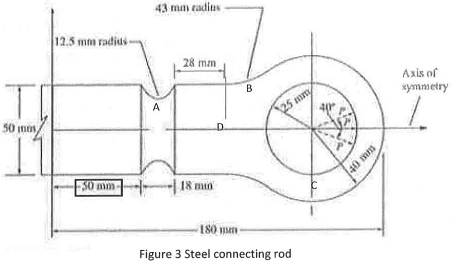
Q2. Perform a FE analysis on Creo 3.0 Simulate for the flat steel connecting rod shown in (extracted from Text Book page 425) Figure 3. You need to simplify the problem using the symmetry and create a coarse mesh first and then refine the mesh appropriately. The thickness of the connecting rod is 10 mm and P= 4 kN. E=200 GPa and Poisson ratio 0.3 for steel.
Perform Plane Stress Analysis:
(a) Estimate the "Stress Concentration Factor" Kt ( Hoop Stress at A/Far field uniform stress) at stress raisers areas identified by letter A and B.
(b) Determine maximum principal stress and the location.
(c) Using the X & Y components of the strain at point D on the x axis, manually calculate X, Y stress components and Z strain components at point D using generalized "Hooks Law". Show all necessary steps of manual calculations
(d) Max principle stress plot.
Perform Plane Strain Analysis:
(a) Estimate the "Stress Concentration Factor" Kt (Hoop Stress at A/Far field uniform stress) at stress raisers areas identified by letter A and B.
(b) Determine maximum principal stress and the location.
(c) Using the X & Y components of the strain at point D on the x axis, manually calculate X, Y, Z stress components at point D using generalized "Hooks Law". Show all necessary steps of manual calculations.
(d) (2D plane stress) and Max principle stress plot.
Perform a 3D analysis:
(a) Estimate the "Stress Concentration Factor" Kt (Hoop Stress at A/Far field uniform stress) at stress raisers areas identified by letter A and B.
(b) Determine maximum principal stress and the location.
(c) Compare the stress and strain components at point D with above two cases.
Please provide your recommendation for the best analysis for this problem. Justify your recommendation with necessary details.
Question 4 -
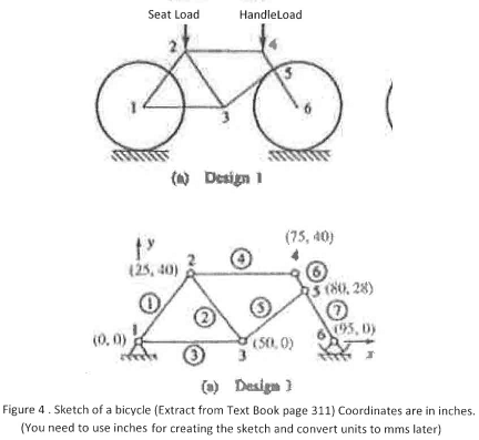
Figure 4 shows a sketch of a bicycle frame. The bicycle frame is to be manufactured with hollow steel pipe segments connected by welds at their ends as shown. Your task:
Create an appropriate model on Creo 3.0 simulate. Assume the weight of the rider 850 N and can be applied to seat and the handle at 5:1 ratio. Perform a static analysis with a trial value of pipe section. (Pipe details can be found in the text book but not limited to that document. However an extract will be uploaded on to Study Desk. If you use a different type you need to indicate the reference in your report)). Following is the design criteria as : Needs to withstand combined 5g vertical and 3g horizontal shock loads. The maximum allowable stress of any member of the frame should be less than 0.66 ultimate strength of the pipe material, no buckling to members 5 and 6, maximum vertical displacement of any joint of the frame (unsupported) less than 3 mm as much as possible. The outer dia of the members should be less than 35 mm. You are free to use combination of pipe sizes as appropriate. Try not to exceed the weight of the bicycle frame more than 15 kgs.
Find the optimized members for the frame to suit above criteria. Show your final design. Justify your design using appropriate FEA result plots sketches etc.
Steel properties: E = 210 GPa, Strength 350 MPa, Poisson ratio 0.3,. Do not consider welds at the joints.