Draw a circuit diagram plus voltage and current waveforms

Assignment Help Electrical Engineering
Reference no: EM13960551

Electrical Power and Drive Systems

Problem 1. A 3-phase power system is represented by the single-line diagram shown in Figure Ql. The per unit (pu) positive, negative and zero-sequence reactances shown are all to a common 100 MVA base.

1328_Electrical Power and Drive Systems.png

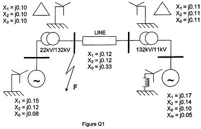
a) Assuming that the synchronous generators remain at their rated voltages, calculate the fault current and fault level for each of the following zero-resistance short circuits at point F in Figure Q:

(i) single line-to-ground,
(ii) line-to-line

Comment on the difference in fault levels for these two types of fault.

b) Calculate also the voltage of the 'healthy' line in case (ii) above.

c) Explain briefly how the solutions to parts (i) and (ii) above will be affected if the fault at point F has an impedance ZF.
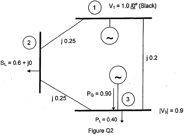
Problem  2. (a)

(i) Explain briefly why an iterative numerical technique is required in load-flow studies of power systems.

(ii) State the general form of nodal voltage equations for a network and derive expressions for the voltage and input reactive power at any node in the network.

(b) The single line diagram of a three-phase power system is shown in Figure Q2. The data for voltages, generation, loads and reactance are all in per unit (pu) to the same MVA base. Using the Gauss-Seidel iterative method, stating any assumptions made, find each of the following after the first iteration:

i) The voltage at busbar

ii) The reactive power Q3 and the voltage angle δ3 at busbar

iii) Explain clearly and concisely how the Gauss-Seidel method should proceed to its conclusion.

946_Electrical Power and Drive Systems1.png

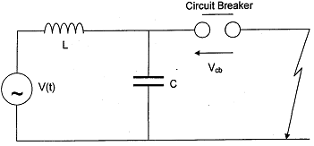
Problem 3. (a) Compare the effects of internal and external events in the generation of over-voltage transients in h.v. power systems. Explain the relevance of these effects to the specification and protection of plant.

(b) Figure Q3 is the single-phase representation of a 3-phase, 50-Hz, power system with negligible resistance. A symmetrical short circuit to earth occurs on the system immediately beyond the circuit breaker.

i) Derive an expression for the voltage across the circuit breaker contacts, Vcb(t), immediately after current interruption if this occurs at a current to prior to natural current zero. You may assume that the supply voltage remains constant at its maximum value, Vm, during the fault and that the arc voltage across the circuit breaker contacts prior to current interruption is negligible.

ii) Given that system voltage VL = 15kV, L = 10mH, C = 4pF and the interruption occurs 11° prior to current zero, show that the voltage Vcb(t) in kV is given by:

Vcb(t) = 12.25(1 - Cos (5000t) 37.22Sin (5000t)

iii) Hence estimate a value for the 'Rate of Rise of the Restriking Voltage' (RRRV), and briefly explain the practical significance of and the factors influencing RRRV.

1600_Electrical Power and Drive Systems2.png

Problem 4. a) Using a half-wave, three-phase, controlled rectifier bridge as an example, explain the phenomenon and effects of 'overlap'. Draw circuit and waveform diagrams as necessary to illustrate your answer.

Derive an expression, in terms of the supply voltage, for the voltage presented to the load during the overlap period.

b) For a p-pulse, controlled rectifier bridge, without flywheel diode, the average dc voltage presented to the load, is given by:

Vdc = P√2Vs/Π.Sin(Π/P)cosα - PωLIL/2Π

Where

Vs = the supply voltage

IL = the line current

L = the source inductance (per phase)

P = the number of pulses per cycle

α = the delay angle beyond the natural commutation point

It is required to provide variable speed control of a 300 V, separately excited, dc motor using a 6-pulse converter. The motor armature current rating is 600A, its speed rating is 1500 rpm and the armature resistance is 30.0 mQ.

The supply frequency is 50 Hz and the source impedance is j0.09 CI per phase.

i) Calculate the minimum line voltage required to operate the motor at its rating with the above arrangement.

ii) Determine the value of a when the motor is operated at 1000 rpm at one third rated torque with a supply voltage VL = 300 V.

Problem 5. a) Draw a circuit diagram plus voltage and current waveforms, to illustrate how the speed of a permanent magnet dc motor may be controlled from a dc supply using a chopper drive.

b) A single-phase, half-controlled full-wave bridge rectifier supplies dc to the armature of a separately excited dc motor. The rectifier is supplied from a 220 V, 50 Hz, single phase supply. The bridge is fired at an angle of 110o and the current in the armature lasts for 110° in each cycle. The motor has an armature resistance of 0.6 Ω and a motor Constant of 0.97 Nm/A. Neglecting rectifier device and overlap volt drops, if the motor emf is 80 V determine:

i) the speed of the motor in rpm,

ii) the average armature voltage, and

iii) average armature current.

Problem 6.

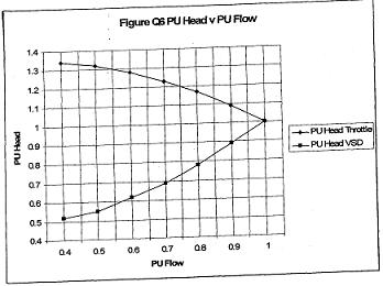
a) Induction motors may present an operator with difficulties when they are connected to a 'weak' supply and are required to start against load. Explain how a Variable Speed Drive (VSD) can provide a better solution than other 'soft-start' methods.

b) A three-phase induction motor is to be used to pump cooling water in an industrial process. It is required to vary the flow rate between 1.0 and 0.4 per unit (pu) and flow rates across this range of values are equally probable over time.

Flow rate can be varied by throttling or by using a VSD. Figure Q6 shows the relationship between pu Head and pu Flow for both methods
At a flow rate of 1 pu the mechanical output power is 4 kW and there are system losses of 0.25 pu comprising:

0.075 pu fixed losses

0.075 pu Torque squared losses 0.1 pu Speed squared losses

Estimate the time taken for the VSD to pay for itself given that electricity costs are 9p per kWh and the cost of installing the VSD is £1000 more than that of the throttling system.

You may assume that:

1 Torque is proportional to Head for both methods.

2 Speed is proportional to Flow for the VSD system and fixed for the throttled system.

575_Electrical Power and Drive Systems3.png

Attachment:- Exam.pdf

Reference no: EM13960551

Questions Cloud

Explain how the allocation process can make a fixed cost : Explain how the allocation process can make a fixed cost appear variable, leading to a poor decision.
Explaining the sensitivity information : Develop and solve a linear optimization model to determine the optimal mix to maximize profit and write a short memo to the president Kathy Chung explaining the sensitivity information in language that she can understand.
Prepare the scope and objectives of the risk management : Prepare the Scope and Objectives of the Risk Management Process section of the Risk Management Plan based on the facts presented in the case study.
What is the cost in the united states of an elkhead beer : Assuming absolute PPP holds, what is the cost in the United States of an Elkhead beer if the price in Canada is Can $2.55? (Round your answer to 3 decimal places.
Draw a circuit diagram plus voltage and current waveforms : Draw a circuit diagram plus voltage and current waveforms, to illustrate how the speed of a permanent magnet dc motor may be controlled from a dc supply using a chopper drive - Calculate the minimum line voltage required to operate the motor at its..
Modifications of the tatham capital budgeting model : Need LP tutorial help involving optimization and the use of Solver. Solve the following modifications of the Tatham Capital Budgeting model (solve each part independently of the others)
Overhead volume variances do not signal that overhead : Overhead volume variances do not signal that overhead costs are in or out of control. Do you agree? Explain.
Manufacturer of several different cheese products : Megley Cheese Company is a small manufacturer of several different cheese products. One of the products is a cheese spread that is sold to retail outlets.
Set of possible rings for purchase : After searching the Internet, you come up with a set of possible rings for purchase. But you have also learned, pricing can vary considerably with diamond purchases. Not wanting to be ripped off, you remember 0S4680 and decide to do a regression a..

Reviews

Write a Review

Electrical Engineering Questions & Answers

  Design an n-channel silicon jfet with pinch off voltage

design an n-channel silicon JFET with pinch off voltage (-2V). The channel is doped with Arsenic and the gate is doped with Boron. the Boron density is 1019 atoms /cm-3 all atoms are fully ionized. The resistance of the channel at zero gate bias i..

  Design an up-down counter with four states

Design an up / down counter with four states (0, 1, 2, 3) using clocked J-K flip-flops. A control signal x is used as follows: When x = 0 the machine counts forward (up), when x = 1, backward (down).

  Find the electric field on the axis of the annulus

Consider a thin annulus of charge extending from p = c to p = d and having a charge density ps. Find the electric field on the axis of the annulus. The asix of the annulus runs through its center and is perpendicular to the plane containing it.

  Explain how a random variable x is normally distributed

A random variable X is normally distributed with mean u = 10 and standard deviation sigma = 1.5. Find the following probabilities: A. P(8 or equal 8.5).

  Explain why single inverting op amp will not work for design

Suppose we need an amplifier with input resistance of 500 kO or greater and a voltage gain of -10. The feedback resistors are to be implemented in integrated form and have values of 10 kO or less to conserve chip area.

  Determine the wavelengths for electromagnetic waves

1. Determine the wavelengths for electromagnetic waves in free space with the following frequencies: 1 kHz, 100 kHz, 1 MHz, 1 GHz. 2. Determine the frequencies for electromagnetic waves in free space with the following wavelengths: 1 cm, 1 m, 10 m..

  What is the allowable signal swing at the collector

Using a 3-V power supply, design a version of the circuit of fig 6.62 from the book. to provide a dc emitter current of 0.5 mA and to allow a +-1-V signal swing at the collector. The BJT has a nominal B=100. Use standard 5 % resistor values

  1 plot the bremsstrahlung emitted intensity vs energy from

1. plot the bremsstrahlung emitted intensity vs energy from a copper target for i both 15 kev and 30 kev electrons ii

  Typical engineering component

Select a typical engineering component which may suffer from corrosion. Describe problems caused by the corrosion. Distinguish form of the corrosion.

  Calculate line current when the transformers are operating

Three 150 kVA, 480V/4000V,60 Hz single-phase transformers are to be installed on a 4000V, 3-phase line. The exciting current has a value of 0.02 pu. Calculate the line current when the transformers are operating at no-load.

  Determine what size of copper wire is required

The generator voltage is 120 V and the lamp voltage should be 110 V or more. Calculate the current drawn by each lamp if its voltage is 110 V and its power is 100 W. Calculate the current in the two-wire line. Calculate the maximum resistance of t..

  What frequency of the siren does a person in the car hear

A car is traveling on a street at 24.6 m/s. An ambulance is behind the car, moving in the same direction and with a speed of 38.7 m/s. The siren on the ambulance is emitting sound at a frequency of 1575 Hz. The speed of sound in the air is 343 m/s..

Free Assignment Quote

Assured A++ Grade

Get guaranteed satisfaction & time on delivery in every assignment order you paid with us! We ensure premium quality solution document along with free turntin report!

All rights reserved! Copyrights ©2019-2020 ExpertsMind IT Educational Pvt Ltd