Reference no: EM13902687
Design and Simulation of a Frequency Division Multiplexer
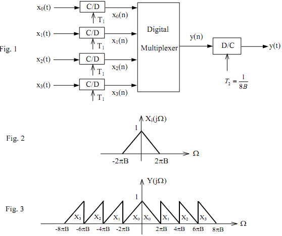
Fig 1 shows a frequency division modulator, which is to convert a number of bandlimited signals to a wide-band frequency division modulated signal. Each of input signals xi(t) (i=0,1,2,3) has a bandwidth of B Hz as illustrated in Fig.2, and is already sampled with T1 = 1/2B. The output signal of the modulator should have a spectrum as shown in Fig.3. The Digital Multiplexer is designed to carry out the modulation in discrete-time domain. It contains upsamplers and digital filters.

These digital filters can be derived from the same lowpass filter, called prototype filter and denoted as H(z) (you can use an FIR filter for this purpose). Assume that B = 4kHz and 4 sinusoidal signals xk(t) are used as input each having a frequency less than 4kHz. In order to distinguish them, you should choose 4 different frequencies. If you wish, you can use four speech signals for such a narrowband to wideband conversion.
You will then convert y(t) back to xi(t) to playback the speech signals.
(a) Develop the multiplexing algorithm to obtain y(n) from xi(n) or y(t) from xi(t). (You might find it easier to work in frequency domain).
(b) Plot your input signals xk(t) and the output signal y(t) with Matlab.
(c) Design a de-multiplxer to convert the "wide-band" signal y(t) to four narrow band signals, i.e., to recover xk(t) from y(t). Plot the recovered signals using the result y(t) you obtained in part
(i), and compare them with your original input signals. (This part is optional. You will get 5 bonus marks if you do it).