Reference no: EM132314818
Neural networks for robot control
Figure 1 shows a two-link robot. The dynamic equations of this robot are shown in the Appendix. Numerical values for relevant parameters used in the equations are given in table
1.The aims of this project are:
1. To implement a given computed-torque controller (CTC) in Simulink for this robot.
2. To use a neural network (NN) to perform the CTC and implement this NN controller in Simulink.
The controllers developed are to be implemented in SIMULINK to demonstrate their effectiveness.
A SIMULINK model of the robot that accepts driving torques in robot joints and generates positions and velocities of the robot joints is also provided to test you controllers.
You are required to work individually. The assessment will be based on the following aspects:
• Your performance in achieving the given milestones.
• A final written report.
Students will be assessed on their progress based on the assessment schedule below. Students present on the dates mentioned in the schedule will be given a mark according to the progress related to the schedule and their understanding of the project. ZERO mark will be given to students who are absent at the scheduled assessment time unless prior written permission has been granted by the lecturer.
Assessment Schedule:
1. Implement a computed-torque controller and demonstrate the performance of this controller using SIMULINK. (by the end of your tutorial session in Week 13).
2. Develop and incorporate a neural network to realise the CTC controller that is implemented in stage 1. Demonstrate the performance of this neural network controller. (by the end of your tutorial session in Week 14).
3. Submit a report (no more than 15 pages) providing the methodology used, listing of SIMULINK programs (of the CTC and NN controller), example outputs and performance comparison and analysis of the controllers designed in stages 1 and 2. (by 12 noon Friday 27th May 2016 - you are welcome to submit early - to the School's reception desk located on the Ground floor of Build X).
Assessment
Submit a type written report (no hand written report will be accepted/marked), in either word or PDF format, (no more than 15 pages) providing the methodology used, listing of SIMULINK programs (of the robot, the CTC and NNC), example outputs and performance comparison and analysis of the controllers (both CTC and NNC).
In particular, the report should address at least the following asepects:
1. Introduction
2. Methods:
a. Simulation model of the robot
b. CTC methods/equations, controller calculation, and CTC implementation in the simulation
c. NNC methods - that including NN structure, training process
3. Results:
a. CTC results - controller gains used, simulation results with error comparisons
b. NNC results - NN training results (accuracy), NNC controller outcomes with error comparison.
4. Discussions and conclusions
5. Simulation models and programs - you should include these in the report and submit the codes/models in the code submission link.
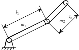
Figure 1. Two link planar IBM robot.
Hints regarding the project:
Technical hints:
1. To build the robot model and to implement the CTC in SIMULINK:
Students will need to put the robot dynamic equations into a MATLAB function in Simulink to simulate the robot. Similarly, to implement the CTC, you will need to put CTC equations (Eq 2) into a MATLAB function in Simulink.
In the attached screen shot of the Simulink Library, you can find the required SIMULINK block under "User-Defined Functions" and then drag the "Interpreted MATLAB Function" icon to their model. You can then double click the icon and provide the name of the function (for example: Robot or CTC). After this is done, you will need to create a function called ‘‘Robot.m' or ‘CTC.m' in the directory that you will run the simulation.
2. To implement an NN controller.
To training the neural network to implement the controller, you will need to generate random inputs that covers the operating range of the robot: θ ∈ [Π, -Π] (rad/sec) θ· ∈ [-5, 5] (rad/sec) and θ¨∈ [-10, 10] (rad/sec2). Then appropriate equations should be used to calculate the controller outputs for these randomly generated inputs. You should refer to the example program that was posted with Week 10 Lecture Notes on vUWS for how to train an NN.
The neural network can be trained to realise the CTC equation (2). However, as there are more variables in equation (2) than in equation (1), it is more efficient to train the NN to learn equation (1). Once an NN is trained to realise equation (1), then the CTC controller can be implemented by replacing the input to neural network for θ¨ by θ¨d + kv(θ¨d - θ) + kp(θd - θ).
This short linear equation can be pre-calculated using mathematical equations before input to the NN. By using this method, the training time for the NN can be reduced significantly!!
Once the NN is trained, you will need to put this NN into another MATLAB function similar to what you have done for CTC.
3. Desired trajectory for the CTC and the NN controller.
To test the effectiveness of the controllers you have designed, you will need some desired trajectories for the robot to follow. You can design your own trajectory planner for this robot and use the controller to follow the trajectories generated. However, to save time, you can also use the sine wave generator in Simulink as your desired trajectories. (Caution: if you do use the sine wave generator, please make sure that the velocity and acceleration of the trajectory agrees with the position signals).
Time schedule hint:
The creation of SIMULINK model of the robot and the implementation of the CTC should be very straightforward. You should aim to finish this in the first week of your project. The NN training, on the other hand, could take some time especially when you are not familiar with the software and if the computer you use is not powerful.
Attachment:- Robotics_Project.rar