Reference no: EM132376749
Assignment : Harmonics
Assignment Description
The purpose of this assignment is to give you some experience in the simulation of a basic power system and the determination of the harmonic content produced by a three-phase grid connected solar system. From this, you will be able to estimate the reduction in the life of
power equipment connected to the system busses because of harmonic induced heating of the equipment insulation. This assignment will also provide some experience in using harmonic filtering, via simulation, to reduce the harmonic voltage distortion produced via the three-phase grid connected solar inverter. The simulation work is best done in Matlab using Simulink, as some basic files will be included to give you a head start on the work.
Introduction
Harmonic distortion of the supply voltage waveform is a major source of temperature rise issues in transformers and rotating machines. The additional harmonic induced temperature rise will result in thermal degradation of the electrical insulation in these pieces of power equipment. As a result of this, the expected service life is reduced. This reduction in service life will require the equipment to be replaced early or it could ultimately lead to a catastrophic electrical failure.
Problem
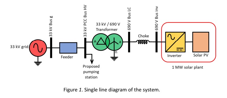
A 1 MW solar instillation is connected to the grid via a long 33 kV feeder. The solar plant operates at a nominal voltage of 690 V via a 6-pulse 3-phase full H-bridge. The PWM modulating frequency is set 500 Hz. The H-bridge feeds the inverter transformer via a choke. Provision is made at the low voltage terminals of the inverter transformer for a 3-phase harmonic filter bank if necessary. The high voltage terminals of the inverter transformer is considered as the common 33 kV bus (PCC). The single line diagram of the system as described above is shown in Figure 1.
It is proposed to connect a pumping station to the 33 kV PCC (Bus B_HV). This pumping station will consist of a standard 3-phase power transformer, associated control and switchgear and an induction motor. This proposed equipment will not specifically specified for high voltage harmonic content operation.
You are therefore tasked to perform a harmonic study on the system, both with and without harmonic filters and to estimate the life of the proposed pumping station transformer and motors.
You’re Task
Your task is to perform the following two investigations on the system, as briefly outlined in the Problem, and then comprehensibly document your findings:
Task 1. Perform a simulation of the system as it stands, without any filtering and determine:
a. The harmonic content of the voltage and current at the 33 kV PCC (Bus B_HV) up to the 40th harmonic. To start you off, a Matlab Simulink simulation (Three_phase_PV_Mod_2016b.slx for Matlab R2016b) of the system is provide. The simulation model with the harmonic currents and voltages at the PCC (Bus B_HV) is shown in Appendix A.
b. Determine the expected life for the following equipment; using the voltage harmonic data up to the 40th harmonic; if supplied from the 33 kV PCC (Bus B_HV) if the ambient temperature is Tamb=40°C, the rated temperature is Trat=110°C, and the rated lifetime of the equipment is assumed to be t2=40 years:
i. Three-phase induction motors (Use k=0.95, l=1.60 and E/R=9.57x103).
ii. Three-phase transformers (Use k= 0.90,l =1.75 and E/R=6.21x103).
Task 2. Perform a simulation of the system with a 3-phase doubled tuned harmonic filter at the low voltage side of the inverter transformer:
a. Connect the filter bank to the output of the inverter choke as shown in Appendix
B. Determine the voltage and current harmonic content at the PCC (Bus B_HV) up to the 40th harmonic.
Note: The tuning frequencies of the two single tuned filters in the simulation are set to the centre frequencies of the first two significant PWM harmonics at 400 Hz and at 600 Hz respectively. The resistance, inductance, and capacitance values are determined from the following parameters: Reactive power at nominal voltage, Tuning frequencies and Quality factor. The quality factor is a measure of the sharpness of the tuning frequency. It is determined by the resistance value. The Reactive power primarily determines the amount of harmonic attenuation the filter will provide.
b. Determine the expected life for the following equipment; using the voltage harmonic data up to the 40th harmonic; if supplied from the PCC (Bus B_HV) with the above filter arrangement in place, if the ambient temperature is Tamb =40°C, the rated temperature is Trat=110°C, and the rated lifetime of the equipment is assumed to be t2 =40 years:
i. Three-phase induction motors (Use k=0.95, l=1.60 and E/R=9.57x103).
ii. Three-phase transformers (Use k= 0.90,l =1.75 and E/R=6.21x103).
Task 3. Comprehensibly document your findings in the form of a neat, concise paper: The paper should have a maximum eight (8) pages, and use the IEEE two-column conference paper template, which will be provided. Make good use of clear well- constructed images and graphics to aid in your reporting. This paper should be presented in a PDF format.