Reference no: EM132314831
Task 1
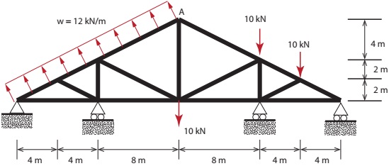
Figure 1: Bridge under load.
The truss shown in Figure 1 is subjected to distributed load along the top left face and point loads at various intervals. Perform a finite element analysis of the truss using Abaqus. Your report should document the following results:
1.The deformed shape of the truss
2.The stress contour of the truss
3.The location of the maximum stress and maximum deflection
Assume that all the members have a square cross section with sides b = 300 mm. The Young's modulus of the material used in the construction of the truss is E = 210 GPa.
In your finite element analysis, use the following:
1. Linear beam element in Abaqus
2. Perform a convergence study by increasing the number of elements along each member of the trus.
You may try to use 2, 4, 8, 16 elements per member, compare and report your observations
3. Use line load when applying the distributed load ω
Task 2
A concrete overpass structure is shown in the figure below. Assume plane strain condition. Let Young's modulus E = 900 kPa and Poisson's ratio ν = 0.2. Determine the values and locations of the maximum tensile and compressive principle stresses occurring in the slope model. Determine also the abslolute maximum displacement magnitude and its location experienced by the slope model. The boundary conditions of the slope model is as follows:
1. The left and right edges are constrained in the horizontal direction
2. The bottom edge is constrained in both horizontal and vertical directions
Considerable amount of experience is necessary to select an optimal mesh so that the results are sufficiently accurate for engineering purposes at the minimum amount of computational cost. Very often, calculations with a series of meshes starting from a coarse one need to be performed, and their results compared. In this task, you are required to follow the best-practice modelling approach. This analysis consist of two parts.
Part 1
The simplest approach is to re ne the mesh uniformly. Start with a coarse mesh by specifying a global seed size hseed = 20 m. Use 4-node quadrilateral elements with mapped feature turned off i.e. use free meshing. When specifying element type,turn off the reduced integration option. Perform a finite element analysis using this mesh and record the results. Then repeat the analysis by specifying a smaller global element sizes hseed = 10 m, 5 m, and 2.5 m. Report on the observations you make with regards to the stress contour, and the value of the maximum tensile and compressive stresses.
You may need to consult the user's manual or the tutorial examples to complete the finite element analyses. A convergence study is to be performed for each of the required values. This study will lead to best estimates and error estimations to these values. The aim of this task is to exercise the best-practice approach in finite element analysis. It is unacceptable to perform the computation with one fine mesh only.
Part 2
Compare the quality of 3-node triangular, 6-node triangular, 4-node quadrilateral and 8-node quadrilateral elements. To evaluate the quality of di erent types of elements, meshes with similar numbers of nodes are generated using each type of element. An element of higher quality will lead to more accurate results. In this part of the task, you will repeat the analysis in Part 1 using hseed = 5 m. Assume that the result obtained with hseed = 2.5 m in Part 1 is accurate enough and will be used as a reference solution. The finite element results from the four di erent elements (3-node triangular, 6-node triangular, 4-node quadrilateral and 8- node quadrilateral) will be compared with this reference solution. Rank the performance of the elements according to their accuracy. Comment on the observations you made.
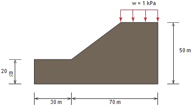
Figure 2: Concrete overpass structure subjected to load.
Report
Your report should include the following key contents:
1.Title page
2. Table of contents
3. Brief description of objective of analysis
4. Description of the methodology which includes (a)the steps/algorithms of calculations
(b) Description of mesh
5. Analysis results, evaluations and discussion (a)Plot of the finite element mesh
(b) Contour plot of displacements
(c) Contour plot of stresses
(d) Tabulated displacements and stresses at required locations (e)Estimation for errors based on a convergence study
6. Conclusions (best estimates of displacement and stresses, error estimation, etc.) and suggestion for further improvement in your analysis