Determine the value of the total parasitic inductance

Assignment Help Electrical Engineering
Reference no: EM131243588

Q1. For Fig 1, the input voltage is dc and positive with the polarity shown. Specify how to implement the switches using a minimal number of diodes and transistors, such that the converter operates over the entire range of duty cycles. The switch states should vary as shown in Fig. 2. You may assume that the inductor current ripples and capacitor voltage ripples are small.

1524_Figure.png

a) Realize the switches using SPST ideal switches, and explicitly define the voltage and current of each switch.

b) Express the on­state current and off­state voltage of each SPST switch in terms of the converter inductor currents, capacitor voltages, and/or input source voltage. 

c) Solve the converter to determine the inductor currents and capacitor voltages.

d) Determine the polarities of the switch on­state currents and off­state voltages. Do the polarities vary with duty cycle?

e) State how each switch can be realized using transistors and/or diodes, and whether the realization requires single­quadrant, current­bidirectional two­quadrant, voltage­bidirectional two quadrant,or four­quadrant switches.

2. A switching converter operates with a switching frequency of 150 kHz. The converter waveforms exhibit damped sinusoidal ringing, initiated by the transistor turn­off transition, which decays slowly but eventually reaches zero before the end of the switching period. This ringing occurs in a series resonant circuit formed by parasitic inductances and capacitances in the circuit. The frequency of the ringing is 10 MHz. During the first period of sinusoidal ringing, the ac inductor current reaches a peak magnitude of 0.5 A, and the ac capacitor voltage reaches a peak magnitude of 150 V. Determine the following quantities:

(a) The value of the total parasitic inductance,

(b) The value of the total parasitic capacitance,

(c) The energy lost per switching period, associated with this ringing, and

(d) The switching loss associated with this ringing.

(e) Derive a general expression for the switching loss, as a function of the switching frequency, ringing frequency, and the ringing voltage and current peak magnitudes during the first period of ringing.

3. In Fig 3 , the switching transition for a switch are shown with following switching characteristics

tri = 80ns

tfv = 80ns

trv = 120ns

tfi = 200ns

Vd = 300V

I0 = 4A

2024_Figure1.png

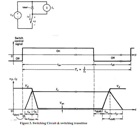
a. Using Fig 3, sketch the instantaneous switching loss for the switch as a function of time.

b. Calculate the switching power loss as a function of the switching frequency in a range 25 ­ 100 kHz, assuming Vd = 300V and I0 = 4A.

c. Calculate and plot the total losses as a function of the switching frequency in a range 25 ­ 100 kHz in the switch when the on­state voltage is Von =1.5V at 4A and the duty ratio of the switch is D = 0.4 (assume tdon=tdoff).

Assumption for Q4:

A transistor having an on­resistance of 0.5 ohm is used. To simplify the problem, you may neglect all losses other than the transistor conduction loss. You may also neglect the dependence of MOSFET on­resistance on rated blocking voltage. These simplifying assumptions reduce the differences between converters, but do not change the conclusions regarding which converter performs best in the given situations.

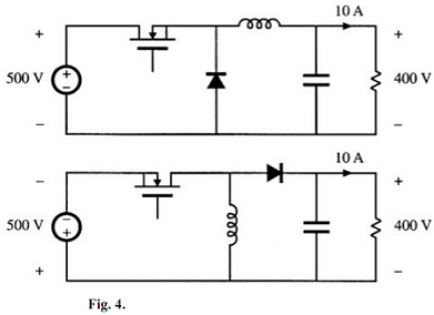
4. It is desired to interface a 500 V dc source to a 400 V, 10 A load using a dc­dc converter. Two possible approaches, using buck and buck­boost converters, are illustrated in Fig. 4. Use the assumptions described above to:

(a) Derive equivalent circuit models for both converters, which model the converter input and output ports as well as the transistor conduction loss.

(b) Determine the duty cycles that cause the converters to operate with the specified conditions. 

(c) Compare the transistor conduction losses and efficiencies of the two approaches, and conclude which converter is better suited to the specified application.

1668_Figure2.png

5. To reduce the switching harmonics present in the input current of a certain buck converter, an input filter is added as shown in Figure 5. Inductors L1 and L2 contain winding resistances RL1 and RL2 respectively. The MOSFET has on­resistance Ron and the diode forward voltage drop can be modeled by a constant voltage VD plus a resistor RD. All other losses can be ignored.

189_Figure3.png

(a) Derive a complete equivalent circuit model for this circuit.

(b) Solve your model to find the dc output voltage V.

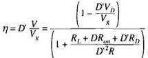
(c) Derive an expression for the efficiency. Manipulate your expression into a form similar to the below equation.

452_Figure4.png

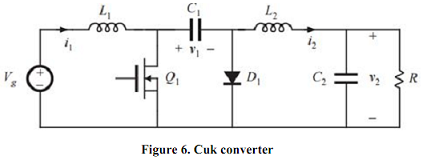
6. In the Cuk converter shown in Figure 6, the MOSFET has on­resistance Ron and the diode has a constant forward voltage drop VD. All other losses can be neglected.

291_Figure5.png

(a) Derive an equivalent circuit model for this converter. Suggestion: if you don't know how to handle some of the terms in your dc equations, then temporarily leave them as dependent sources. A more physical representation of these terms may become apparent once dc transformers are incorporated into the model.

(b) Derive analytical expressions for the converter output voltage and for the efficiency.

(c) For VD = 0, plot V2/Vg vs. D over the range 0 ≤ D ≤ 1, for (i) Ron/R = 0.01, (ii) Ron/R = 0.1, (iii) Ron/R = 1. Conclude from the result. 

(d) For VD = 0, plot converter efficiency vs. D over the range 0 ≤ D ≤ 1, for (i) Ron/R = 0.01, (ii) Ron/R = 0.1, (iii) Ron/R = 1. Conclude from the result.

Reference no: EM131243588

Questions Cloud

Displays the contents of the resulting destination array : In your algorithm you will need to compare the keys of the source arrays, picking the smallest one to copy to the destination. You'll also need to handle the situation when one source array exhausts its contents before the other.
Correlation analysis and covariance analysis : Differentiate between correlation analysis and covariance analysis of data with the help of a suitable example.
Bootstrapping and irr discounting : Use bootstrapping to calculate Z (0, 1), Z (0, 2) and Z (0, 3), and obtain P0[0, 3], the present value of a three-year annuity paying €1 per year.
Comments into the code : Make sure that you put comments into the code for each class with your name, the class number and name, Week 8 project, date, and my name." Please have a nice, readable format for your work. Separate the different files and output neatly so that I..
Determine the value of the total parasitic inductance : 534 ECE Homework. A switching converter operates with a switching frequency of 150 kHz. Determine the following quantities: The value of the total parasitic inductance, The value of the total parasitic capacitance, and  The energy lost per switching ..
Construct an original fallacy argument of that type : Identify and define the fallacy. For example, appeal to tradition, false dichotomy, etc. Explain why this type of fallacy is a bad way of reasoning. Construct an original fallacy argument of that type.
Which imply a violation of the no arbitrage assumption : Which of the following necessarily imply a violation of the no-arbitrage assumption? Assume T > 0 and ? > 0, and that all portfolios are self-financing.
Explain the security vulnerabilities associated : Briefly describe your mobile device and another device currently on the market that uses a different OS. Explain the security vulnerabilities associated with each device. Explain the security solutions that would address the vulnerabilities. Final..
Choose the most appropriate relationship between prices : For each of the pairs of A and B in Table, choose the most appropriate relationship between prices at time t ≤ T out of =, ≥, ≤ and ?, where ?

Reviews

Write a Review

Electrical Engineering Questions & Answers

  Plot the i-v and p-v curves of the panel

Plot the I-V and P-V curves of the panel, An ideal PV panel model can be used to understand the operation of the P&O method. Let the panel parameters be n=1, T=300K, IL=3A, and Io=10-10A.

  Write general form of natural response for capacitor voltage

Consider a source-free parallel RLC circuit having alpha =10^8 s^-1, omega-sub-zero = 10^3 rad/s, and omega-sub-zero * L = 5 ohm. a) Show that the stated units of omega-sub-zero * L are correct. b) Compute s_1and s_2.

  Determine whether the discrete signals are periodic

Determine whether the discrete signals below are periodic. If the signal is periodic, determine the number of samples per period. (a) x[n]=cos(πn) (b) x[n]= -3sin(.01πn) (c) x[n]= 1+cos((πn)/2)

  What is transformer efficiency when output voltage is 120v

a single phase 10kVA, 2400/120 V transformer has the following equivalent measurements (referenced to high side): Rc 64k ohms, Xm 9.6k ohms, Re 19.3 ohms, Xe 73.3 ohms. if the secondary load is Zl = 5 angle 30 degrees ohms

  What is the corresponding result for the impedance matrix

What is the corresponding result for the impedance matrix of two series-connected T-networks?

  Shows the direction of force on a positive point charge

Is the force per unit charge produced by a charge or charge distribution.

  Find the net heat transfer for the process in kj

50 kg of a certain gas is contained within a piston-cylinder assembly. the gas undergoes a processwhich the pressure volume relationship is PV = constant. (n=1.5) the given conditions as follows : p1= 6 bars, v1=0.2 cubic meters ,and v2= 0.4 cubic..

  Determine the dc self bias line expression relating id to vg

a) By applying Kirchoff's voltage law to the output (DC) circuit loop determine the DC Load Line, i.e. an expression relating Id to Vds. Comment briefly on the significance on the result, with respect to the slope and x-axis intercept.

  Design the circuit using as few d flip flops as possible

Assume A is the MSB and B is the LSB. The circuit produces an output of 1 if and only if the sum of the current 2-bit input and the previous 2-bit input is equal to 6. Design the circuit using as few D flip flops as possible. Draw the state diagra..

  How to design a simple unipolar drive circuit

Design a simple unipolar drive circuit such that the electrical time constant is 2 msec at phase turn-on and 1 msec at turnoff. The stepping rate is 300 steps per second. A three-phase variable-reluctance stepper motor has parameters.

  How to take a decimal number and get it in binary numbers

How to take a decimal number and get it in binary numbers such as  98= 0110 010

  Calculate force due to gravity f_gravity

Two hanging balls, each with a mass of 10g, have equal charges. One ball is hung by an insulated thread. Another ball held by an insulated rod.

Free Assignment Quote

Assured A++ Grade

Get guaranteed satisfaction & time on delivery in every assignment order you paid with us! We ensure premium quality solution document along with free turntin report!

All rights reserved! Copyrights ©2019-2020 ExpertsMind IT Educational Pvt Ltd