Reference no: EM132777596
You are a post graduate engineer, employed at a leading automotive manufacturer, working in the research and development department. Your line manager has set you a task to test the static loading and forces applied to their new FCV prototype car to confirm the design team's theoretical analysis. In order for you to determine the unknown forces, you must undertake an incline vehicle test at the companiesrolling road test facility and carry out analytical analysis on the data collated; you are to present the analysis to your line manager for appraisal.
Task 1
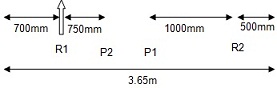
Prior to the test commencement, the reactions at the front and rear wheels of the FCV car shown below must be calculated. The self-weight of the car equates to a UDL along its full length of 6kN/m, the incline test will replicate two people sat in the vehicle, one driving (P1) and one rear passenger (P2) with weights of 152.906kg and 122.325kg respectively.
During the incline test, the car accelerates up a rolling road with a slope of 1 in 10, increasing its speed from 3.0 m/s to 12 m/s, while travelling up the rolling road a distance of 100 m, against a frictional resistance of 0.8kN. Determine, using D'Alembert's principle:
(a) The free-body diagram representing the car driving up the hill.
(b) The tractive effort between the driving wheels and the road surface.
(c) The work done during the period of the acceleration.
(d) The average power developed.
(e) Use the conservation of energy method to validate the solutions determined using D'Alembert's principle.
For incline testing analysis, the car's mass (kg) is to be taken as the equivalent of the mass of ‘R2'.
You work as a material engineer and have been tasked with investigating thermal efficiency issues with hot water and fuel storage tanks manufactured by your company. These tanks are currently made from steel, but your company plan on introducing polymer and polymer composite wall tanks to increase their product range, improve cost effectiveness and widen applications of use for the company's products.
After researching differing materials in relation to their thermal heat transfer and thermal efficiencies for the manufacture of the new proposed storage tank ranges, the technical engineering director as requested a presentation of your findings to the following tasks.
Task 2
1) A bi-metallic strip is used as part of the thermostat fitted to one of the companies hot water tanks, the bi-metallic strip consists of copper and zinc strips which have the same length of 17.5 cm at a temperature of 18 °C.
a) What will be the difference in length of the strips at a temperature of 105°C?
b) The strips were riveted together at 18°C to form a bi-metallic strip. Assuming that it bends into an arc when heated. Determine which metal will be on the outer side of the arc and what will be the radius of the arc at 105 °C. Thickness of each strip is 1.25 mm.
2) A waste handling machine requires a cube shaped steel oil tank of side length 100mm to be designed which will be subject to a fluid pressure of 80MN/m². The oil tank as an overflow valve fitted to the top of the tank, the tank is completely filled with oil at an optimum operating temperature of 50°C, under your investigations in the R&D dept it was found that the oil temperature could rise to 78°C depending on the operating time and external environmental temperature. Ignoring the fluid pressure, determine how much oil will overflow from the tank. Take the volumetric coefficient of expansion of the oil as 764 x 10-6 °C -1 and the linear coefficient of expansion of steel as 12 x 10-6 °C -1.
Task 3
A composite wall tank is proposed to be used to heat feed water for a heat exchanger; the tank consists of a main steel tank (10mm wall thickness), then an air gap and an outer tank covering made from a polymer foam (8mm thickness). The steel tank contains waterat 90°C when the atmospheric temp is 15°C. The thermal conductivity of mild steel is 50 W/mK and the heat transfer coefficients for the inside and outside of the steel tank are 2800 and 11 W/m2K respectively. The thermal conductivity of air and the rigid foam are 0.16 k/W and 0.035 W/mK respectively.
Calculate:
i) The rate of heat loss per unit area of tank surface.
ii) The temperature of the outside surface of the tank, including the % heat loss and thermal efficiency.
The steel used for the composite wall tank is to be replaced with a polymer based material in order to save upon weight, cost and thermal losses. You are to compare the results found from your analysis of the composite wall steel tank in Task 2i and 2ii, to that of using at least two different types of polymers instead of steel, and two different types of rigid foam for the tank application. Determine, for each polymer composite wall combination:
iii) The rate of heat loss per unit area of tank surface.
iv) The temperature of the outside surface of the tank, including the % heat loss and thermal efficiency.
After completion of your comparative analysis, your manager informs you that the R&D dept are planning to use a pre-installed polymer composite tank for a dual purpose, firstly to store the company's main hot water supply and to secondly heat feed water that supplies their heat exchanger test rig. The heat exchanger feed water pipe will be attached to the outside surface of the composite tank so it forms a series of rings, the heat from the outer surface of the tank will be transferred to the water in the feed pipe. (Assume 100% thermal heat transfer).
The heat exchanger produces dry steam at 221°C from feed water (temperature dependant on your solutions to Task 2vi) at a rate of 2.25kg/s. The heat exchanger receives heat energy at a rate of 2.3MW from the fuel used. The specific heat capacity of water is 4187J/kgK and its specific latent heat of vaporisation is 2257J/kg.
You are tasked with comparing how changes in the temperature and thermal efficiency of the composite wall tanks analysed in Task 3 would affect the thermal behaviour of the heat exchanger, by determining:
v) The heat energy received per kilogramme of steam produced.
vi) The output power of the heat exchanger and its thermal efficiency.
vii) Compile a report comparing and explaining the effects of using the different composite wall tanks upon the thermal behaviour / efficiency of the heat exchanger system. Include a summary table of results.
Task 4
The polymer composite wall tank is to be scaled up for a large industrial application, you are currently working on a safety device for the release of the water in the tank to prevent overflow situations developing, Your plan is to use a floatation device connected to a release valve via a chain to prevent accidental over-filling of the tank. Your design involves a solid, wooden floatation device measuring 2.5m long, 1.75m wide and 0.3m in depth. Take the specific density of wood as 0.57. You need to determine:
i) Whether the device floats in water, and the resulting net force.
ii) If it floats, how much of the device is beneath the surface?
iii) The device is anchored by a steel bar of length 0.6m and diameter 60mm which is suspended from a chain attached to the underneath of the device. Determine the tension in the chain when the bar is fully immersed. The density of steel is 7860kg/m3.
Attachment:- static loading and forces.rar