Reference no: EM132288022
Electrical Circuit Fundamentals Assignment Questions -
Question 1 - (a) Using a practical example, describe what an electric circuit is.
(b) With the aid of appropriate MATLAB plot(s) differentiate between electric current, dc current and ac current. Also, state the units used to measure each of them.
(c) What unit is used to describe an electrical charge?
Assume that the total charge entering an electric circuit is q(t) = 60tsin(120πt) mC.
(d) Compute the charge at the time instant t = 1/60 sec.
(e) Calculate the value of the current at time t = 1/60 sec.
Question 2 - Assume that the current i passes through a device with the resistance R in an electric circuit.
(i) State the mathematical formula to be used to calculate the voltage v that has fallen across the device. Find the voltage if R =20 Ω and i = 2 mA.
(ii) State the mathematical formula for the power P dissipated in the device by the current. Find the power for the values obtained in Part (i).
(iii) State the three different but equivalent units used to measure the electrical voltage.
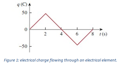
Question 3 - The electrical charge flowing through an electrical element is plotted in Figure 1. Sketch the corresponding current as the function of time through the element.
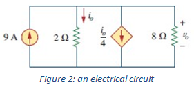
Question 4 - Apply the Ohm's law, the Kirchhoff voltage law (KVL) and the Kirchhoff current law (KCL) to find the current i0 and the voltage v0. In the electrical circuit shown in Fig. 2.
Question 5 - In the circuit in Figure 3
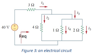
(i) Find the Req in the circuit
(ii) Determine the current through each resistance i1 to i5.
(iii) Determine the power dissipated by each resistor and the power delivered by the independence voltage source. Confirm that the power delivered by the independent source is the same as the power absorbed by the resistors
(iv) Use LTspice program to create the circuit and compute for all the resistor voltages and currents.
(v) Compare your simulation measurements with the results of your calculations.
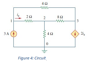
Question 6 - Using the Cramer's rule and the basic laws for electrical circuit analysis, compute the voltages at the nodes of the electrical circuit shown in Figure 4.
Question 7 - Apply Thevenin's theorem on the electrical circuit of Figure 5.
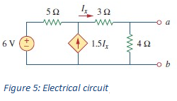
(a) Compute the equivalent Thevenin circuit to the left of the terminals a-b.
(b) Using your results in Part (b), compute the current passing through the resistor RL = 8 Ω.
Question 8 - Apply Norton's theorem on the electrical circuit of Figure 6.
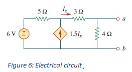
(a) Compute the Norton equivalent circuit to the left of the terminals a-b.
(b) Using your results in Part (b), compute the voltage fallen across the 3- Ω resistor in the circuit.