Reference no: EM13338976
1. The variation of (2S/dt + Q) with Q, of a basin is given by Q = 0.0015(2S/dt + Q)2 + 0.195(2S/dt + Q) - 0.3833. The outlet structure is a weir with crest length L = 1.5 m set at elevation Y = 30.5 m and discharge coefficient kw = 0.4. The storage of the basin increases linearly from 0 at Y = 30.5 m to 16,980 m3 at Y = 35 m and the initial water level is at Y = 30.9 m.
(i) Determine the peak outflow rate when the following inflow hydrograph is routed through this basin.

(ii) What is the design storage and water surface elevation at the peak outflow rate.
2. (a) A combination gutter section has the dimension W = 0.5 m, SL = 0.008 m/m, Sx = 0.02 m/m, and a = 0.05 m. The Manning roughness factor is 0.016. Determine the discharge in the gutter if the spread is 2.0 m. Estimate the flow intercepted by the curb opening inlet placed in the composite gutter if the inlet length is 1.75m.
(b) Evaluate the spread and depth at the curb for a triangular gutter section carrying a design discharge of 0.09m3/s and having a uniform cross slope of 0.022m/m, Manning's roughness of 0.015, and longitudinal slope of 0.014m/m.
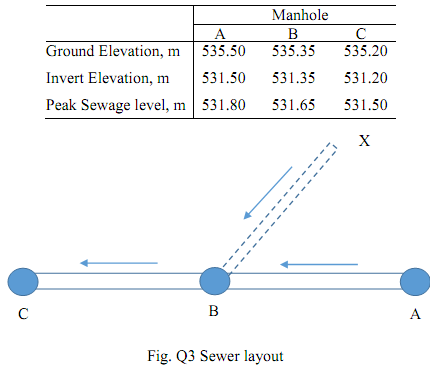
3 An existing trunk sewer ABC has a diameter of 600 mm (see Fig. Q4). The length of sewers between successive manholes A to B and B to C is 50 m. The sewage flow from a new development at X (ground elevation = 536.35m) to the north of the trunk sewer is planned to be conveyed in a new sewer line XB (distance = 50m) to discharge in manhole B. The average flow is estimated to be 300 Lpcd, and the peaking factor is 3. The following limitations are given Vmin = 0.75 m/s, Vmax = 3.0 m/s, n = 0.013, minimum cover = 1.5 m. Determine the following:

(i) The maximum population that can be served from the new development without exceeding the capacity of the trunk sewer.
(ii) Diameter, slope, and invert elevations of sewer XB.
The following data is provided:
4 A gravel-packed well with an effective diameter of 36 in is to be constructed in an aquifer with T = 2.6 x 10⁴ gpd/ft and S = 2.3 x 10⁻⁵. The design flow of the well is 1000 gpm. Calculate the drawdown at the well (use r which is the distance from the pumping well = 18 in) with total withdrawals from storage after (a) 1 min, (b) 1 h, (c) 1 day, (d) 1 month, and (e) 1 yr of continuous pumping, at design capacity. Repeat the calculations for r = 1m and 100m. (conversions: 1m3/d/m = 80.517 g/d/ft, 1 in = 25.4 mm, 1 gpm = 5.45 m3/d)