Reference no: EM133651336
Mechatronics Design
Homework - Transistors
1 Introduction
In this assignment, students will solve some design problems using semiconductor parts. The first task will have students solve some circuits, the second will have students design, build, and test circuits with parts from the provided kits.
2 Procedure
Transistor circuit
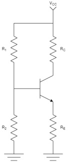
Figure 1: A Transistor Circuit
Consider the circuit in figure 1. Determine the base, collector, and emitter voltages and currents, as well as the currents through R1 and R2. Assume that the transistor is ideal, and that its β = 10. Further, determine for what values of R1, R2, Rc, and Re is the transistor in its three regions (Cutoff, Saturation, and Active). To do this, you will need to find the two inequalities with respect to Vcc. Finally, replace the transistor with a PNP transistor, how does this change the results?
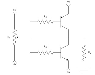
Figure 2: A half bridge circuit
Half Bridge
The circuit presented in figure 2 is known as a half-bridge. This circuit can be used to apply a positive or negative current to a load, and is useful for tasks such as driving motors. Determine the relationship between the poten- tiometer's position α and the current through the load RL. To do this, you can model the potentiometer as two resistors R1 = αRP and R2 = (1 - α) RP .
Once you have the equations, assume a load of 30?, that requires 2W of power with a 1k? potentiometer. Choose a common resistor value for RB that will allow this circuit to to supply the appropriate power. Assume the transistors are ideal with β = 100.
Motor Driver
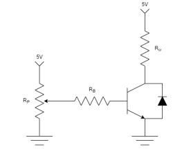
Figure 3: Single-sided motor driver circuit.
Design
For this problem, consider the motor, transistors, and potentiometer in the provided kit. Design the circuit in figure 3 to drive this this motor based on the signal from the potentiometer. To do this, first measure the resistance of the motor and the potentiometer. The motor will consume about 0.5W of power max, design RB to support this power level. There are two transistors in your kit, for this problem, use the S8050 NPN Transistor. For this problem, since we are using a real transistor, you cannot assume that the transistor is ideal. Use the provided datasheet for the transistor to design RB. Once you have found the ideal RB, consider the available resistor values, and choose the best one. Determine the equations for the output voltage of the potentiometer. the load current, and the transistor's collector voltage as a function of the position of the potentiometer α. Provide plots of these curves.
Build
Now that you have the circuit designed, build the circuit on your breadboard. Be sure to double check which lead is which on the transistor with the datasheet, and make sure the fly-back diode is in the correct configuration.
Test
For the test portion, wire your arduino to sample the potentiometer's output voltage as well as the transistors collector voltage with the ADC. Note that since there is only one ADC, you will have to sample them separately, but the time difference should be inconsequential given the time scales of the motor. Plot these voltages relative to each other (x axis is the potentiometer output voltage, y axis is the transistor collector voltage) over the ideal curve.
Discussion
Finally, discuss the design decision you made, and these topics:
Why did you choose the resistor for RB, what would have happened if you picked one on the other side of of the ideal value?
At what values of alpha does the transistor change transition between operational regions?
How well did the measured performance line up with what you expected?
Why are we able to ignore the motor's inductance for this experiment?
Based on the measured performance, and the information in the datasheet, what do you think the actual collector current is? Explain.
How does the diode effect the circuit?