Reference no: EM13910567
What is expected from you?
A final design report that has to include the following:
1. All alternative designs and the final design selection
2. For the final design, submit
• Detailed Drawings using solid work (2D and 3D)
• Supporting analysis (get help from the design steps shown in the project),
• Bill of materials (including quantity needed and cost).
3. The report has to be clearly written and well organized.
Problem Statement:
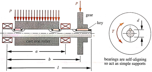
Designing a shaft and its components (i.e. keys and retaining rings) for industrial roller assembly driven by gear as shown in the figure 1. The roller extends over 80% of length a and is centered in that dimension. The roller occupies 95% of the exposed shaft length between the bearing faces. The cast iron roller and the gear are subjected to constant Radial Loads of 132kN/m and 3.3kN, respectively, while the shaft is subjected to fluctuating torque between 115 and 230 N.m.Loads and geometrical data are provided in table 1.
|
a [mm]
|
b [mm]
|
l [mm]
|
P [kN]
|
p [kN/m]
|
T min [N.m]
|
T max [N.m]
|
|
400
|
550
|
600
|
3.3
|
132
|
115
|
230
|
Figure 1 Schematic diagram of preliminary design of roller driven by gear
• The gear and bearings are supported by shoulders and held in place by retaining rings.
• The gear and roller transmit torque through keys.
• The width of each bearings is 30 mm.
• A minimum design factor is chosen as 2.
• The maximum allowable deflection at the roller is 30 µm.
• The maximum allowable torsional deflection between the gear and the roller is 0.2 deg.
Requirements:
It is required to design the above shaft by performing the following tasks:
1. Sketch a general shaft layout, indicating means
1.1 To locate the gear, bearings, and roller
1.2 To transmit the torque.
1.3 Datum for the axial length and axial dimensions at different positions.
2. Perform a force analysis to find the bearing reaction forces.
3. Draw shear and bending moment, and torque diagrams.
4. Determine the critical locations for stress design.
5. Select suitable material for the shaft (initial selection).
6. Determine critical diameters of the shaft based on fatigue stresses at the critical locations; make choose of another suitable material if the design requirement is not achieved with the initial selection.
7. Make any other dimensional decisions necessary to specify all diameters and axial dimensions. Sketch the shaft to scale, showing all proposed dimensions.
8. Check the deflection at the gear, and the slopes at the gear and the bearings for satisfaction of the recommended limits in Table 7-2, and limitation given in the problem.
9. If any of the deflections exceed the recommended limits, make appropriate changes to bring them all within the limits.
10. Suggest better materials that may improve the deflection without changing the overall dimensions.
11. Draw detailed drawings of shafts and its components using solid work (2D and 3D), showing keys slots, grooves etc.
12. Prepare a list of required materials and their cost, as well as estimation of manufacturing cost.
13. Reference any source you used in this project, with proper citation. (Internet sites, books, notes, etc.....).
RIGIDITY ANALYSIS (for Stepped Shaft)
Following approach can be used to calculate the deflection of a stepped shaft
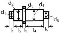
Use an equivalent diameter for estimating the shaft deflections. The equivalent shaft diameter is given by:
de = l1d1 + l2d2 + l3d3 + l4d4 + l5d5/l
Use formula from the Appendix to calculate deflection at the gear location with
I = Π/64 d4e.
|
Find first four non-zero terms of two linearly independent
: Show that x = 0 is a regular singular point. Find two linearly independent solutions about this point using the Frobenius Method. Find the first four non-zero terms of two linearly independent solutions y1 (x) and y2 (x) .
|
|
Objectives and major elements of your risk management plan
: Describe the objectives and major elements of your risk management plan.Identify the top five (5) risks involved within your solution. Prioritize the risks and provide your rationale.Suggest strategies to prevent and mitigate the risks identified in ..
|
|
Is strategy supports the three components of organizational
: In your initial post, share an analogy that illustrates how IS strategy supports the three components of organizational strategy. The three components of organizational strategy in the managerial levers model are organizational variables, control var..
|
|
Describes one of the project management principles
: Which of the following describes one of the project management principles? A. Tell teams what you want, but don't tell them how to do it. B. Give team members clear instructions how to get the job done.
|
|
Determine the critical locations for stress design
: Perform a force analysis to find the bearing reaction forces, draw shear and bending moment, and torque diagrams and determine the critical locations for stress design.
|
|
Outline the basic theories behind motivation
: Outcomes and Objectives Illustrate how managers mobilize people for competitive advantage. a.Outline the basic theories behind motivation.
|
|
Statistical analysis system
: SAS (pronounced "sass"), which is short for Statistical Analysis System, began when it set out to create statistical software to help agricultural researchers who were studying the effects of soil, seeds, and the weather on crop yields. In 1970, rese..
|
|
What is the mean and standard deviation for preoperative
: What is the mean and standard deviation for preoperative T score for CVLT Acquisition?
|
|
Committee of fiction corporation
: In this assignment you are to submit the PowerPoint Presentation for the term paper. This is the first partof your term paper submission. Part A is a persuasive PowerPoint presentation of up to 15 slides that youwill present to the Executive Committe..
|