Reference no: EM131038091
Question 1- The circuit shown in Figure 8-3 represents a(n)_________.
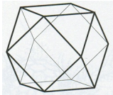
-synchronous BCD decade counter
-BCD-to-decimal decoder
-synchronous four-bit binary counter
-asynchronous BCD decade counter
Question 2- A MOD 12 and a MOD 10 counter are cascaded. The input clock frequency is 60 MHz. Determine the counter output frequency.
-1,500 kHz
-5 MHz
-6 MHz
-500 kHz
Question 3- What is the output state of a MOD-64 counter after 92 input pulses if the starting state is 000000?
-0101102
-0111102
-1001002
-0111002
Question 4- Which of the following best describe the characteristics of a MOD-16 counter?
-Sixteen possible counts, a maximum count of 1510, arid frequency division by a factor of eight
-Eight possible counts, a maximum count of 710, and frequency division by a factor of eight
-Eight possible counts, a minimum count of 710, and frequency division by a factor of sixteen
-Sixteen possible counts, a maximum count of 1510, arid frequency division by a factor of sixteen
Question 5- For the circuit shown above, what would be the values of Q output of the Flip-Flop-2 (FF2) during times t3 and t5?
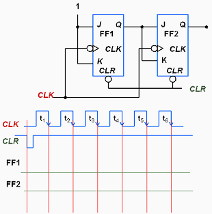
-0 and 0 respectively
-0 and 1 respectively
-1 and 0 respectively
-1 and 1 respectively
Question 6- Four positive edge-triggered D flip-flops are used to store a 4-bit binary number as shown here. Determine if the circuit is functioning properly, and if not, what might be wrong.
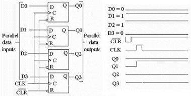
-The circuit is functioning properly.
-Q2 is incorrect: the flip-flop is probably bad.
-A bad connection probably exists between ff-3 and ff-4, causing ff-3 not to reset
-The input to flip-flop 3 (D2) is probably wrong: check the source of D2.
Question 7- How many, flip-flops are required to design a MOD-56 counter? Give the result as integer number.
Question 8- The figure shows an integrated 3 bits synchronous counter with synchronous load. An automatic reload is used to reset the count. What type of counter is it?
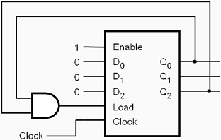
-MOD-3
-MOD-5
-MOD-6
-MOD-8
Question 9- In a MOD-10 counter we can distinguish________ different states.
-Four
-Nine
-Ten
-Sixteen
-None of the above
Question 10- Which of the following is one of the primary functions performed by registers?
-NOR
-AND
-XOR
-memory
Question 11- Bidirectional shift registers can shift data either right or left.
True
False
Question 12- Refer to the Shift-Register circuit and waveforms in Figure 9-2. What is the value of the data stored in Q3, Q2, Q1 and Q0 respectively at time 'X'?
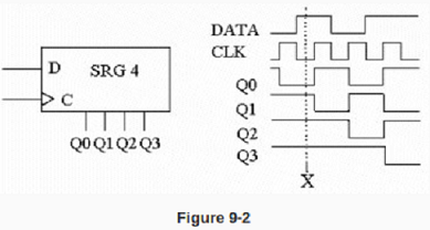
-0101
-0110
-1110
-0111
Question 13- Which of the DATA OUT waveforms in Figure. 9-3 is correct?

DATA OUT a.
DATA OAT d.
DATA CUT b.
DATA OUT C.
Question 14- What type of register is shown in Figure 9-4?
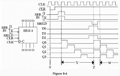
-Serial/parallel-in parallel -out register.
-Parallel-access shift register.
-Serial-in parallel-out register.
-Parallel-in parallel-out register.
Question 15- Referring to Figure 9-4, what action takes place during the period marked 'W' on the timing diagram?

-The register has gone into the counter mode and is counting the value of the parallel data previously stored on parallel inputs.
-The register has just been cleared and the clock pulses are being toggled through the register.
-The data is shifted from the parallel inputs to the parallel outputs.
-Data is being serially shifted through the register.
Question 16- What type of device is shown in Figure 9-5?
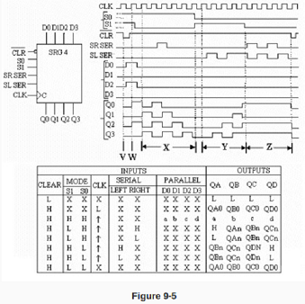
-Parallel-in parallel-out shift register with bidirectional data flow
-4-bit bidirectional universal shift register
-2-bit serial-in 4-bit parallel-out bidirectional shift register.
-2-way parallel-in serial-out bidirectional register.
Question 17- Referring to Figure 9-5, what action takes place during the interval labeled 'Z' on the timing diagram?

-Data is shifted right through the register
-Serial data is entered into the register
-The operation of the register is inhibited no changes occur on the outputs
-Data is shifted left through the register
Question 18- Referring to the Function Table in Figure 9-5, taking the CLEAR S1 and S0 inputs all HIGH will do what?

-It will cause the parallel data inputs to be loaded and passed to the parallel data outputs
-It will inhibit the operation of the register
-It will reset the parallel registers and inhibit the serial data inputs
-The exact response will depend on what values are loaded into the parallel data inputs
Question 19 - A serial data path needs a 2000 ns delay. Which output from the circuit (Shift-Register) below will provide the correct delay? Assume that the data is presented to the inputs right before the rising edge of the clock and also the propagation time of the internal flip-flops is very small.
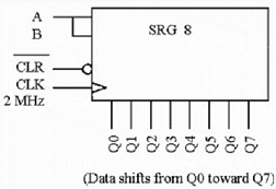
-Q0
-Q1
-Q4
-None of the above
Question 20- What type of register accepts data inputs one bit at a time and outputs all its data bits at the same time?
-Serial in/Serial out
-Serial in/Parallel out
-Parallel in/Serial out
-Parallel in/Parallel out
Question 21- The state diagram given above corresponds to a circuits that performs the following function:
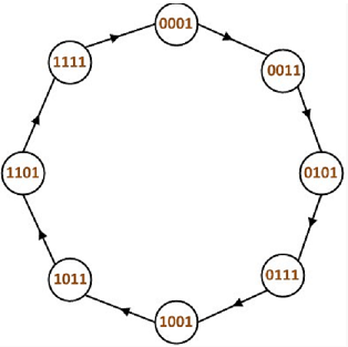
-Four bit Shift-Register
-Four bit up-counter that counts odd numbers
-Four bit down-counter
-None of the above
Question 22- How many D Flip-Flops are required to implement the circuit that performs the above State Diagram

-Three
-Four
-Eight
-Sixteen
Question 23-
|
Present State
|
Next state
|
|
|
|
|
|
|
|
|
|
|
0
|
0
|
0
|
0
|
1
|
1
|
1
|
1
|
|
0
|
0
|
0
|
1
|
0
|
0
|
0
|
0
|
|
0
|
0
|
1
|
0
|
0
|
0
|
0
|
1
|
|
0
|
0
|
1
|
1
|
0
|
0
|
1
|
0
|
|
0
|
1
|
0
|
0
|
0
|
0
|
1
|
1
|
|
0
|
1
|
0
|
1
|
0
|
1
|
0
|
0
|
|
0
|
1
|
1
|
0
|
0
|
1
|
0
|
1
|
|
0
|
1
|
1
|
1
|
0
|
1
|
1
|
0
|
|
1
|
0
|
0
|
0
|
0
|
1
|
1
|
1
|
|
1
|
0
|
0
|
1
|
1
|
0
|
0
|
0
|
|
1
|
0
|
1
|
0
|
1
|
0
|
0
|
1
|
|
1
|
0
|
1
|
1
|
1
|
0
|
1
|
0
|
|
1
|
1
|
0
|
0
|
1
|
0
|
1
|
1
|
|
1
|
1
|
0
|
1
|
1
|
1
|
0
|
0
|
|
1
|
1
|
1
|
0
|
1
|
1
|
0
|
1
|
|
1
|
1
|
1
|
1
|
1
|
1
|
1
|
0
|
The state table given above implements the following circuit:
-Modulo 16 up-counter
-Modulo 16 down-counter
-4-bit Shift Register
-None of the above
Question 24 To implement the circuit that performs the state table given above we require_______ flip flops:
|
Present State
|
Next state
|
|
|
|
|
|
|
|
|
|
|
0
|
0
|
0
|
0
|
1
|
1
|
1
|
1
|
|
0
|
0
|
0
|
1
|
0
|
0
|
0
|
0
|
|
0
|
0
|
1
|
0
|
0
|
0
|
0
|
1
|
|
0
|
0
|
1
|
1
|
0
|
0
|
1
|
0
|
|
0
|
1
|
0
|
0
|
0
|
0
|
1
|
1
|
|
0
|
1
|
0
|
1
|
0
|
1
|
0
|
0
|
|
0
|
1
|
1
|
0
|
0
|
1
|
0
|
1
|
|
0
|
1
|
1
|
1
|
0
|
1
|
1
|
0
|
|
1
|
0
|
0
|
0
|
0
|
1
|
1
|
1
|
|
1
|
0
|
0
|
1
|
1
|
0
|
0
|
0
|
|
1
|
0
|
1
|
0
|
1
|
0
|
0
|
1
|
|
1
|
0
|
1
|
1
|
1
|
0
|
1
|
0
|
|
1
|
1
|
0
|
0
|
1
|
0
|
1
|
1
|
|
1
|
1
|
0
|
1
|
1
|
1
|
0
|
0
|
|
1
|
1
|
1
|
0
|
1
|
1
|
0
|
1
|
|
1
|
1
|
1
|
1
|
1
|
1
|
1
|
0
|
-Three
-Four
-Eight
-Sixteen