Reference no: EM132223660
Question 1. Consider the circuit of Figure P2-1 with Ri = 10 kΩ. and Rf. = 50 kΩ.
a. Determine the closed-loop voltage gain.
b. Determine the input impedance of the circuit.
c. Determine the ideal output impedance of the circuit
d. Determine the peak input voltage vi(peak) for which linear operation is possible.
e. Determine the output voltage for each of the following values of input voltage: = vi = 0 V, -1 V, 2 V, -3V, 4V
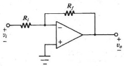
FIGURE P2-1
Question 2. consider the circuit of Figure P2-3 with Ri = 10Ω and Rf = 50 kΩ.
a. Determine the closed-loop voltage gain.
b. Determine the ideal input impedance of the circuit.
c. Determine the ideal output impedance of the circuit.
d. Determine the peak input voltage vi(peak) for which linear operation is possible.
e. Determine the output voltage for each of the following values of input voltage: vi = 0 V, -1 V, 2 V, -3V, 4V
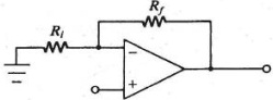
Figure P2-3
Question 3.
For the circuit of Problem 2-1 with vi = -2 V, assume that an external load RL = 2kΩ is connected to the to the output. Determine the total op-amp output current.
Question 4.
Consider the circuit of Figure P2-7 with R = 1 kΩ.
a. Determine the transcondnetauce.
b. For vi= 10 V, determine iL for RL = 500 Ω.
c. Repeat. (b) for RL = 1kΩ
d. Determine the maximum value of RL for linear operation.
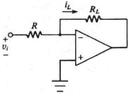
FIGURE P2-7
Question 5. Consider the circuit of Figure P2-8 with R = 5 kΩ.
a. Determine the transconductance.
b. For vi = 2 V, determine iL for RL = 8 kΩ.
e. Repeat (b) for RL= 16 kΩ.
d. Determine the m.aximurn value of RL for linear operation,
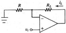
FIGURE P2-8
Question 6. Consider the circuit of Figure P2-9 with R = 2 kΩ.
a. Determine the transconductance.
b. For vi = 6 V, determine iL for RL, = 1.2 kΩ
c. Determine the maximum value of RL, for linear operation.
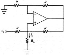
FIGURE P2-9
Question 7. Consider the circuit of Figure P2-13 with R1 = 2 kΩ and R2 = 8 kΩ.
Determine the value of β.
b. For ii= 0.6 mA and RL, = 1 kΩ, verify linear operation.
c. Determine iL for the condition of (b).
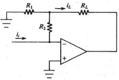
FIGURE P2-13
Question 8. Consider the circuit of Figure P2-15 with Rf = 100 kΩ, R1 = 100 kΩ R2 = 50 kΩ, and R3 = 25 kΩ
a. Write an equation for vo in terms of the three input voltages.
b. Determine Vo for v1 = 10 V, v2 = 3 V, and v3 = -7 V.
c. Determine vo, for v1 = - 8 V, v2 = -4 V, and v3 = 5 V.
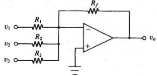
FIGURE P2-15
Question 9. The circuit of Figure P2-20 is a two-input noninverting linear combination circuit Show that the output voltage vo, is given by
vo = (R3 + R4)/(R3(R1 + R2)) (R2v1 + R1v2)
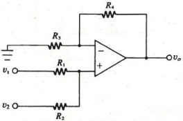
FIGURE P2-20
Question 10. In a certain signal-processing system, it is necessary to combine and modify the levels of four signals, v1, v2, v3, and v4, The desired combination vo is to be formed as follows,
vv = 2v1 + 5v2 - 10v3 -20v4
The following requirements are imposed:
a. no more than 2 op-amps
b. Rin ≥, 10 kΩ at all inputs
c. all resistance values ≤ 500 kΩ
Design a circuit to rform the function.
It is desired to add four signets to form a composite signal vo, as follows:.
v0 = v1 + v2 + v3 + v4