Reference no: EM13318787
1. A section of a mine has the layout as shown in figure 1 below with airway resistances as marked. If the flow into the mine section is 100 m3/s determine the airflows and pressure drop in each of the branches.
2. If the flow into the section in figure 1 is 200 m3/s determine the airflows in each branch.
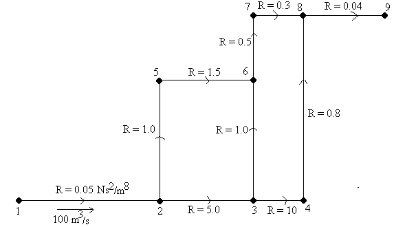
Figure1 In the network shown in figure 1, if the airflow required in airway 5-6 is specified as 30m3/s and the airflow in airway 1-2 is unspecified, determine the pressure drop and airflow in each of the airways.
3. In the network illustrated in figure 1, if a fixed pressure fan developing 3 kPa is installed in branch 8-9 what are the flows and pressure drops in each of the branches? Remove the restrictions from the previous question.
4. In the network illustrated in figure 1, if a fan with the characteristic curve listed in figure 2 is installed in branch 8-9 what are the flows and pressure drops in each of the branches? Remove the fan from question 4.
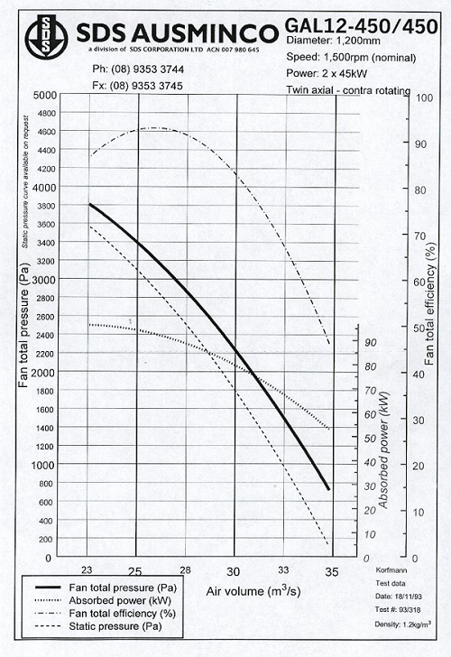
Figure: Fan Characteristic curve
5. In the network illustrated in figure 1, if a fan with the characteristic curve listed in figure 2 is installed in branch 8-9 and roadways 2-5 and 5-6 are sealed with each having a resistance of 1000 Ns2/m8 what are the flows and pressure drops in each of the branches?
Part B: Ventsim
An underground mine is to be designed from near the base of an open pit that is 100m deep. A decline will extend down some 140m below the pit floor, travelling adjacent to a sub vertical orebody. Three drilling / production sub levels will branch off the main decline every 40 vertical metres, starting at 60m below the pit floor. Main production will be from the bottom two levels. A ventilation shaft some 400m away (outside the pit boundary) extends from the mine base to the surface, connecting all sub levels. An exhaust fan on the shaft will need to pull 150m3/s to supply the mines production needs. Fresh air is supplied to the mine via the main decline.
1. Conceptually design a mine ventilation network incorporating the three simple sub levels. Ensure air is supplied equally to each level.
2. Due to power restrictions, main exhaust fan power must not exceed 200kW. What diameter shaft should be mined ?
3. Emergency plans require stench gas to be delivered from the decline portal to all parts of the mine. What is the maximum time for the stench gas to be delivered to all areas of the mine.
Suggested Steps
1. Construct an RL database with a surface level from 0 to -100 and subsequent RL levels -160, -200, and -240.
2. Draw in a decline from the surface (at -100) with nodes placed at every sub level to allow the break-offs to be established. Two ways are recommended to draw horizontal airways between levels. Either use the RIGHT mouse button to draw while in PLAN view - this will allow the RL to be manually selected from a drop down list OR use the arrow keys (up or down) to step between levels while drawing the airway with the LEFT mouse button.
3. The base sub-level should be drawn across to the shaft location. To create the shaft, simply click on the connecting horizontal airway with the RIGHT mouse button, and manually select the surface RL to connect the shaft to the surface. The remaining sub-levels can be joined into the shaft at a later date.
4. A quick way to join the other sub levels into the vertical vent shaft is to click on 'ALL LEVELS' to display all levels of the mine, and spin the network into a cross section view with the rotation button. Then simply connect the appropriate sub-level drive across to the shaft (the sub-level drive will be 'break' into the shaft)
5. Once a rudimentary network is created, airway characteristics (size etc) can be established. If a group of airways have the same characteristics, simply EDIT one airway to the correct value, and use the COPY/PASTE tool bar button, use the RIGHT mouse button on the airway to copy those attributes, and then use the LEFT mouse button the paste those attributes to other airways.
6. The type of fan required is not known at this stage, so EDIT the airway, and fix the airflow to the required 'I50m3/s. Set the shaft to ROUND 2.4m diameter.
7. SIMULATE the network, correcting any errors that arise. Airflows should be distributed through the entire network. To even out the airflows between levels (the top level will naturally draw more air), regulators (resistance values) will have to be placed on the upper sub-level shaft accesses. This will force more air to the lower levels. Re-simulate and continue to adjust until airflows are approximately correct.
8. To ensure exhaust shaft power consumption is not excessive, use the INFO tool bar button on the FIXED shaft. The estimated power consumption of the FIX can be reduced if necessary by adjusting the shaft diameter and re-simulating.
9. Stench gas distribution can be simulated by placing a contaminant source (the smoke tool bar button) on the decline access airway. Simulate using the GAS button to distribute the stench gas. Switch the data display to 'TIME' to display time for gases to be distributed. Distribution of stench gas can be animated by using the scroll bar on the LEGEND box.