Reference no: EM131034105
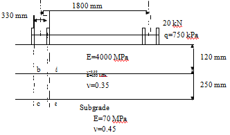
1. For the three layer system shown in Figure 1 below, points b and d are located exactly under the centre of tyres and at the bottom of the surface layer while points c and e are located directly under b and d and at the top of the subgrade. The surface layer is asphalt and is assumed to be isotropic. Determine tensile strain at points b and d and compressive strain at points c and e in these two cases:
Case 1:The base and subgrade are isotropic materials
Case 2: The base and subgrade are cross anisotropic materials

2. In the logging season, the traffic count recorded for the Double Bailey logging unit shown in Figure 2 below is 9000 passes per year. The average axle loads are shown below. The steering axle is single axle-single tyre and all other axles are tandem axles with dual tyres. Determine the total traffic load experienced by this road over one year period, expressed in ESA. If the traffic growth is 3.0%, determine the cumulative traffic in 30 years design period in ESA, SARa, SARc, SARs.

3. The traffic data in Table 6 shows the number of daily axle loads for four axle configurations (Sigle Axle-Single Tyre (SS), Single Axle-Dual Tyres (SD), Tandem Axles-Dual Tyres (TD), Tridem Axles-Dual Tyres (TRD). Determine the cumulative standard axle repetitions (SAR) for the asphalt concrete, subgrade and cemented material base, if the design period is 15 years, the geometric traffic growth rate is 2.5%.
Table: Daily number of axle loads for the different axle load configurations.
|
SS
|
N/Day
|
SD
|
|
TD
|
N/Day
|
TRD
|
N/Day
|
|
(kN)
|
|
(kN)
|
N/Day
|
(kN)
|
|
(kN)
|
|
|
|
|
|
|
|
|
|
|
|
60
|
30
|
70
|
5
|
110
|
7
|
130
|
6
|
|
|
|
|
|
|
|
|
|
|
70
|
10
|
80
|
10
|
120
|
30
|
150
|
28
|
|
|
|
|
|
|
|
|
|
|
80
|
12
|
90
|
15
|
130
|
12
|
170
|
35
|
|
|
|
|
|
|
|
|
|
|
90
|
10
|
110
|
12
|
140
|
20
|
180
|
15
|
|
|
|
|
|
|
|
|
|
|
100
|
20
|
130
|
10
|
150
|
15
|
190
|
4
|
|
|
|
|
|
|
|
|
|
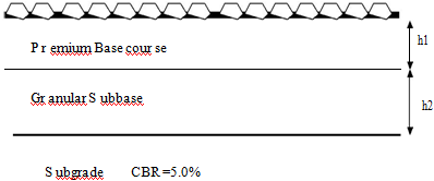
4. You have been asked to design unbound pavement structure with chip seals in a locality with subgrade of CBR =5.0 %, see Figure 3. The cumulative design traffic during the design period is 10*106 ESA. If there are three alternatives of the subbase
course materials with CRB values: 20, 25, and 30%. Determine the thickness h1 and h2 for each subbase option.

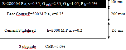
9. The pavement cross section shown in Figure 4 below is designed to carry 20*106 ESA. Use Circly to model the unbound materials and subgrade as cross anisotropic
materials with sublayering and determine the critical pavement responses under a full standard axle load. Determine the cumulative damage factors for project reliability 97.5%. If the pavement design is insufficient redesign the pavement cross section to carry the design traffic. Use the performance function shown below. Use also NZ supplement if necessary.
