Reference no: EM133781867
Introduction to computer engineering
ASSIGNMENT: COUNTERS AND REGISTERS
Question 1: The following figure is a synchronous MOD-16 counter:
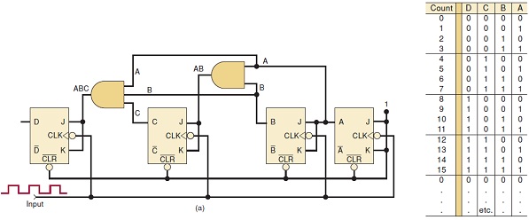
a) Determine fmax for the counter shown if tpd for each FF is 50 ns and tpd for each AND gate is 20 ns. Compare this value with fmax for a MOD-16 ripple counter.
b) What must be done to convert this counter to MOD-32?
c) Determine fmax for the MOD-32 parallel counter.
Question 2: A 10-bit ripple counter has a 256-kHz clock signal applied.
a) What is the MOD number of this counter?
b) What will be the frequency at the MSB output?
c) What will be the duty cycle of the MSB signal?
d) Assume that the counter starts at zero. What will be the count in hexadecimal after 1000 input pulses?
Question 3: The following figure is a MOD-6 counter and its corresponding transition diagram:
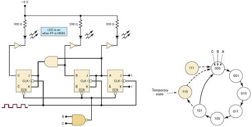
a) What will be the status of the LEDs when the counter is holding the count of five?
b) What will the LEDs display as the counter is clocked by a 1-kHz input?
c) Will the temporary 110 state be visible on the LEDs?
Question 4: A four-bit ripple counter is driven by a 20-MHz clock signal. Draw the waveforms at the output of each FF if each FF has tpd = 20 ns. Determine which counter states, if any, will not occur because of the propagation delays.
Question 5: Answer the following questions:
a) Describe the operation of the circuit shown below.
b) Represent its output using a time-diagram.
Question 6: For a 74ALS138 (see datasheet at Texas Instruments website), what input conditions will produce the following outputs?
a) LOW at ¯Q6
b) LOW at ¯Q3
c) LOW at ¯Q5
d) LOW at ¯Q0 and ¯Q7 simultaneously
Question 7: For each item, indicate whether it is referring to a decoder, an encoder, a MUX, or a DEMUX.
a) Has more inputs than outputs.
b) Uses SELECT inputs.
c) Can be used in parallel-to-serial conversion.
d) Produces a binary code at its output.
e) Only one of its outputs can be active at one time.
f) Can be used to route an input signal to one of several possible outputs.
g) Can be used to generate arbitrary logic functions. [
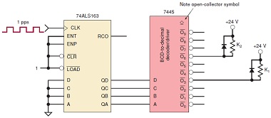
Question 8: A technician wires the outputs from a BCD counter to the inputs of the decoder/ driver. The circuit is depicted attached:
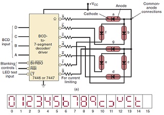
He applies pulses to the counter at a very slow rate and observes the LED display, which is shown below, as the counter counts up from 0000 to 1001. Examine this observed sequence carefully and try to predict the most probable fault. Justify your answer.
Question 9: A counter is needed that will count the number of items passing on a conveyor belt. A photocell and light source combination is used to generate a single pulse each time an item crosses its path. The counter must be able to count as many as one thousand items. How many FFs are required? Justify your answer
Question 10: Construct a MOD-10 counter that will count from 0000 (zero) through 1001 (decimal 9). You must include the sketch of your circuit and the explanation about how it works.
Question 11: Explain how many AND gates are required to decode completely all of the states of a MOD-32 binary counter. What are the inputs to the gate that decodes for the count of 21? Justify your answer.
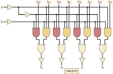
Question 12: Answer the following questions:
Determine the input conditions required for each Z output in the figure given below to take on the logic level of its corresponding I0 (bits I0a, I0b, I0c, I0d) input. Justify your answer.
Repeat for I1 (bits I1a, I1b, I1c, I1d). Justify your answer.
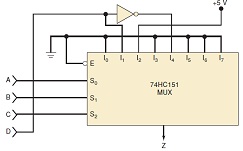
Question 13: The circuit given below shows how an eight-input MUX can be used to generate a four-variable logic function, even though the MUX has only three SELECT inputs. Three of the logic variables A, B, and C are connected to the SELECT inputs. The fourth variable D and its inverse D‾ are connected to selected data inputs of the MUX as required by the desired logic function. The other MUX data inputs are tied to a LOW or a HIGH as required by the function.
a) Set up a truth table showing the output Z for the 16 possible combinations of input variables.
b) Write the sum-of-products expression for Z and simplify it to verify that:
Z = C‾BA‾ + DC‾B‾A + D‾CB‾A‾
Question 14: Show (that is, draw the sketch) how to connect the 74ALS174 so that it operates as a serial shift register with data shifting on each PGT of CP as follows: Serial input In other words, serial data will enter at D5 and will output at Q0.
Question 15: Examine the 74HC165 function table and determine:
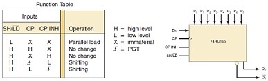
a) The conditions necessary to load the register with parallel data. Justify your answer.
b) The conditions necessary for the shifting operation. Justify your answer.
Question 16: Add another flip-flop, E, to the counter into the figure below. The clock signal is an 8-MHz square wave.
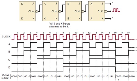
What will be the frequency at the E output? What will be the duty cycle of this signal? Justify your answer.
Repeat (a) if the clock signal has a 20 percent duty cycle. Justify your answer.
What will be the frequency at the C output? Justify your answer.
What is the MOD number of this counter? Justify your answer.
Question 17: Draw a synchronous, MOD-32, down counter. Briefly explain its operation.
Question 18: Answer the following questions:
a) Design a synchronous counter using J-K FFs that has the following sequence: 000, 010, 101, 110, and repeat. The undesired (unused) states 001, 011, 100, and 111 must always go to 000 on the next clock pulse.
b) Redesign the counter of part (a) without any requirement on the unused states; that is, their NEXT states can be don't cares. Describe (compare) the states with the design from a).
Question 19: Answer the following question:
Using its truth table, show how a 16-input multiplexer such as the 74150 is used to generate the function:
Z = A‾B‾C‾D + BCD + AB‾D‾+ ABCD‾